ã€Background Description】
With the improvement of the quality of life and the acceleration of the pace of life, people increasingly need to pay attention to their health. This project intends to design a body parameter test system based on cloud platform + APP + device, using pulse sensors, infrared sensors, and weak signal detection Circuits, etc. realize the collection of human body parameters, and the data is uploaded to the cloud for storage through wireless networks or other methods, and a web-side interactive interface is provided to build a human body parameter management platform for users.
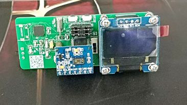

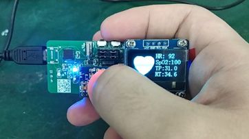
Materials used and physical drawings
Main control: STM32F103
Compilation environment: MDK4.7
RT-Thread version: 2.0.0
ã€hardware design】
1. MCU system circuit
This system uses STM32103C8T6 as the main control chip to collect sensor data on the one hand, and process the data through algorithms on the other hand and forward it to the cloud server. Therefore, two ADC interfaces are connected to the sensor during circuit design. For the STM32 system, its necessary components also include a startup mode selection circuit, a crystal reset circuit, etc. In the design, I also added indicator lights and buttons as spares. The STM32 system circuit is shown in Figure 4. The power supply voltage of STM32 and the voltage of the heart rate and temperature sensors are all 3.3V. Therefore, if a 5V voltage is used for power supply, voltage conversion is also required. This system uses the LDO regulator LM1117 to convert 5V to 3.3V. For the part of the power supply and switch, the system uses the MICO USB interface to supply power and download the program. This part of the circuit is shown in the figure.

STM32 system circuit
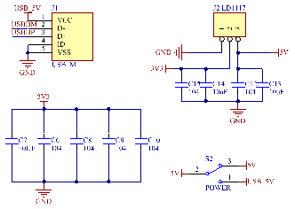
Power switch circuit
2. USB to serial port circuit
Using USB as the system program download interface, the level needs to be converted to communicate with the STM32 serial port. This system uses CP2102 as the conversion chip. CP2102 has a high integration level, built-in USB2.0 full-speed function controller, USB transceiver, The crystal oscillator, EEPROM and asynchronous serial data bus (UART) support the full-function signal of the modem without any external USB devices. The working principle of CP2102 is similar to that of other USB-UART switching circuits. The USB port of the PC is virtualized as a COM port through the driver to achieve the purpose of expansion. The circuit design of this part is shown in the figure.
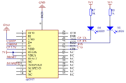
USB to serial port circuit
3. Body temperature sensor circuit
The body temperature sensor uses the characteristic curve of the thermistor and temperature to measure body temperature. The collected signal is transmitted to STM32 after two-stage filtering and amplification. The temperature measurement range is 30°C-44°C. When the 3.3V voltage is used for power supply, its temperature corresponds to the collection The voltage range is 2.127—1.193V. The circuit of the body temperature sensor is shown in the figure.
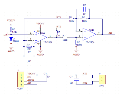
Body temperature sensor circuit
4. Heart rate sensor circuit
The heart rate sensor uses the Pulse Sensor sensor, which has an open source algorithm, easy to use, and low cost. Its principle is to use photoplethysmography to measure heartbeat by measuring human pulse light transmittance. PhotoplethysmoGraphy (PPG) is a non-invasive detection method for detecting changes in blood volume in living tissues by photoelectric means. When a beam of a certain wavelength irradiates the surface of the fingertip skin, the beam will be transmitted to the photoelectric receiver through transmission or reflection. In this process, the light intensity detected by the detector will be weakened due to the absorption and attenuation of the fingertip skin muscle and blood. The absorption of light by skin and muscle tissue remains constant throughout the blood circulation, while the blood volume in the skin changes pulsatingly under the action of the heart. When the heart contracts, the peripheral blood volume is the largest, and the light absorption is also The largest, the smallest detected light intensity; the opposite is true when the heart is in diastole. The maximum detected light intensity makes the light intensity received by the light receiver show a pulsating change, and the change of the volume pulse blood flow can be obtained by converting this light intensity change signal into an electrical signal. The sensor uses a green LED with a peak wavelength of 515nm and a light sensor APDS-9008 with a light sensitivity of 565nm to collect heart rate parameters. Because the pulse signal frequency is low, the signal amplitude is small, and it is susceptible to various interferences, so filtering and enlarge. A low-pass filter and operational amplifier MCP-6001 are used in the back stage of the sensor to filter and amplify the signal. The circuit of the heart rate sensor is shown in the figure.

Heart rate sensor circuit
5.WiFi module
The WiFi module uses the ESP8266 module. When using this module, you need to design its external circuit, including power supply circuit, reset circuit, mode selection circuit and other parts. The completed circuit diagram is shown in the figure.
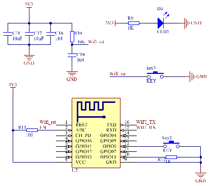
WiFi module circuit
ã€software design】
1. Main chip programming
The programming of STM32 is developed based on RT-Thread. In addition to system initialization, in the main program, the following functions are completed:
Collect the AD data of the sensor through the internal AD interface;
Process the data through algorithms;
Pack the processed data and provide a WiFi module to send to the server;
Feed the dog.
Design according to the above 4 points, and the program flow chart is shown in the figure.
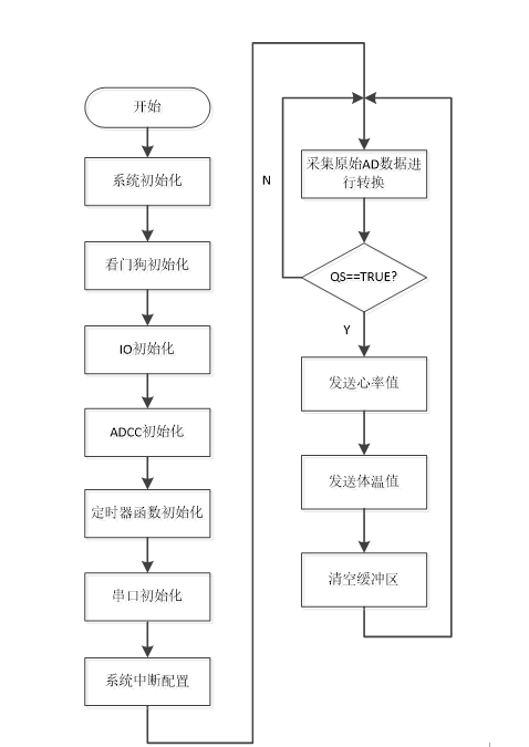
Main program flow chart
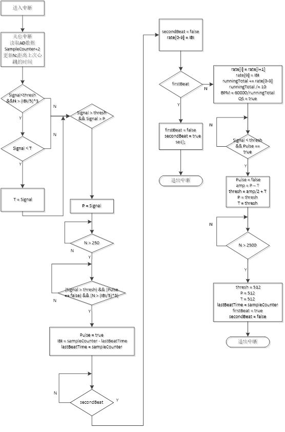
2. Heart rate acquisition algorithm
The goal of the heart rate acquisition algorithm is to find the continuous moment of the instantaneous heartbeat and measure the time interval (IBI) between the two. We can do this by following the predictable shape and pattern of the PPG waveform. When the heart pumps blood into the human body, a pulse wave (a bit like a shock wave) travels along all the arteries to the end of the capillary tissue where the pulse sensor is attached to each beat. The actual blood circulation is much slower than the pulse wave propagation.
Start tracking events from point T on the PPG shown in the figure below. When the pulse wave passes under the sensor, the signal value rises rapidly, and then the signal falls back to the normal point. Sometimes the two-way cut (downward spike) is more pronounced than others, but usually the signal stabilizes to background noise before the next pulse wave flush. Since waves are repetitive and predictable, you can choose almost any identifiable feature as a reference point, such as peaks, and calculate the heart rate by the time between each peak. However, this may be erroneously read from the dichotomous cut and may also be inaccurate for baseline noise. Ideally, finding the moment when the heart beats requires accurate BPM calculations, heart rate variability (HRV) studies, and pulse transit time (PTT) measurements.

Heartbeat PPG waveform
For the calculation of heartbeat, this algorithm measures the instant when the signal crosses 50% of the amplitude during the rapid rise. BPM is derived from each beat of the average of the previous 10 IBI times. First, there must be a normal sampling rate with sufficient high resolution to obtain a reliable measurement of the time between each beat. To this end, I used an 8-bit timer on the STM32 so that an interrupt would be thrown every millisecond. This has a sampling rate of 500Hz and a beat resolution of 2mS. Next, it is necessary to track the highest and lowest values ​​of the PPG wave to obtain accurate amplitude measurements. The variables P and T represent peak and valley values, respectively. The threshold variable is initialized to 512 (the middle value of the analog range) and changes during running time to track the point at 50% of the amplitude, as we will see later. A time period of 3/5 IBI must pass before the T update to avoid noise and false readings from the gap in the binary classification. Subsequently, grab a large variable runningTotal to collect IBIs, and then transfer the content of rate[] and add it to runnungTotal. The oldest IBI (11 times ago) is not at position 0, and the updated IBI is placed at position 9, then the array is averaged and BPM is calculated. The last thing to do is to set the QS flag. If there is no beat event within 2.5 seconds, the variable used to find the heartbeat will be reinitialized to the start value.
By using timer interrupts, our beat search algorithm runs in the background and automatically updates variable values. The overall algorithm flow chart is shown in the figure
3. Server software and web design
The server side adopts the cloud server provided by Alibaba Cloud. Its data transmission protocol is MQTT protocol. The measurement collection side is used as the device side of MQTT, and the cloud server is used as the server side of MQTT. The received data is stored in SQL and displayed on the web page. MQTT protocol data transmission The process is shown in the figure.
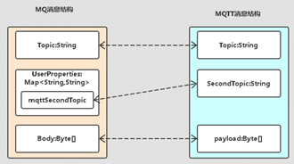
MQTT data transmission flowchart
The designed web page is shown in the figure
4. APP software design
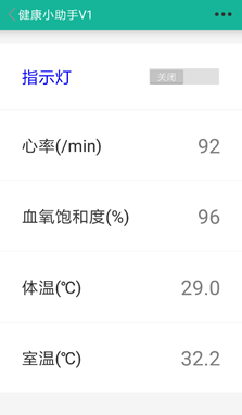
After the mobile terminal APP is opened for the first time, it will manually configure the network. When the designated WIFI signal is searched for, it will connect, and then monitor the TCP port, analyze the received data packet, and then display the data on the screen. The completed APP is shown in the figure below.
5. Host computer software design
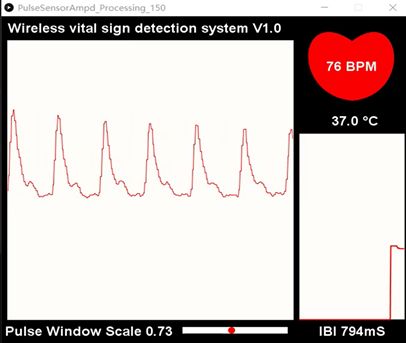
The upper computer software is designed based on JAVA. It receives and analyzes the data packets transmitted by the measuring terminal through the port, and visually displays the real-time status of the heart rate through graphics. The working interface is shown in the figure.
[Introduction to the use of RTT]
This section briefly introduces the use of SPI and serial communication in the RTT involved in the use of OLED and WIFI modules in this system. It also introduces the calling process of functions, the use of key functions, and the calling of device drivers.
1.OLED
OLED and chip communicate through SPI protocol, and the device driver usage process is roughly as follows:
(1) Define the device object, call rt_spi_bus_attach_device() to mount the device to the SPI bus
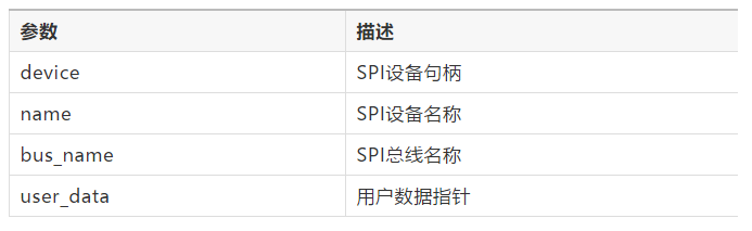
rt_err_t rt_spi_bus_attach_device(struct rt_spi_device *device, const char *name, const char *bus_name, void *user_data)
This function is used to mount an SPI device to the specified SPI bus, register the SPI device with the kernel, and save user_data to the SPI device device.
b. SPI bus naming principle is spix, SPI device naming principle is spixy, spi10 in this project means that it is mounted on spi1 device. a. First, you need to define the SPI device object device
c. The SPI bus name can be viewed by entering the list_device command in the msh shell to determine the SPI bus to be mounted on the SPI device.
d. user_data is generally the CS pin pointer of the SPI device, and the SPI controller will operate this pin for chip selection during data transmission.
The source code of rt_hw_ssd1306_config() in the bottom driver drv_ssd1306.c of this project to mount the ssd1306 device to the SPI bus is as follows:
#define SPI_BUS_NAME "spi1" /* SPI bus name*/#define SPI_SSD1306_DEVICE_NAME "spi10" /* SPI device name*/static struct rt_spi_device spi_dev_ssd1306; /* SPI device ssd1306 object*/static struct stm32_cs spi_cspi; Pin selection*/static int rt_hw_ssd1306_config(void){ rt_err_t res; /* oled use PC8 as CS */ spi_cs.pin = CS_PIN; rt_pin_mode(spi_cs.pin, PIN_MODE_OUTPUT); /* Set chip selection pin mode to output* /res=rt_spi_bus_attach_device(&spi_dev_ssd1306,SPI_SSD1306_DEVICE_NAME, SPI_BUS_NAME, (void*)&spi_cs);if (res != RT_EOK){ OLED_TRACE("rt_spi_bus_attach_device!"); return res;}}
(2) Call rt_spi_configure() to configure the SPI bus mode.
After mounting the SPI device to the SPI bus, in order to meet the clock and data width requirements of different devices, it is usually necessary to configure the SPI mode and frequency parameters. The mode of the SPI slave device determines the mode of the master device, so the mode of the SPI master device must be the same as that of the slave device. The two can communicate normally only if they are the same.
rt_err_t rt_spi_configure(struct rt_spi_device *device, struct rt_spi_configuration
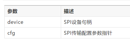
After mounting the SPI device to the SPI bus, this function must be used to configure the transmission parameters of the SPI device. This function will save the mode parameter pointed to by cfg in the device, and this configuration information will be used when the device calls the data transfer function.
The source code for configuring SPI transmission parameters in rt_hw_ssd1306_config() in drv_ssd1306.c at the bottom of this project is as follows:
static int rt_hw_ssd1306_config(void){ /* config spi */ {struct rt_spi_configuration cfg; cfg.data_width = 8; cfg.mode = RT_SPI_MASTER | RT_SPI_MODE_0 | RT_SPI_MSB; cfg.max_hz = 20 * 20 1000 *1000; /* 42MHz,ssd1306 4-wire spi */ rt_spi_configure(&spi_dev_ssd1306, &cfg);}
(3) Use rt_spi_transfer() and other related data transfer interfaces to transfer data.
After the SPI device is mounted on the SPI bus and the relevant SPI transmission parameters are configured, a series of SPI device driver data transmission functions provided by RT-Thread can be called.
struct rt_spi_message *rt_spi_transfer_message(struct rt_spi_device *device, struct rt_spi_message *message)
This function can transmit a series of messages, and the user can flexibly set the value of each parameter of the message structure, so that the data transmission method can be conveniently controlled.
The source code of the function for sending instructions and data is as follows:
rt_err_t ssd1306_write_cmd(const rt_uint8_t cmd){ rt_size_t len; rt_pin_write(DC_PIN, PIN_LOW); /* Command low level*/ len = rt_spi_send(&spi_dev_ssd1306, &cmd _TRAC_write, 1) (" . %d",len); return -RT_ERROR;} else {return RT_EOK; }}rt_err_t ssd1306_write_data(const rt_uint8_t data){ rt_size_t len; rt_pin_write(DC_PIN, PIN_HIGH); /* Data high level*/ len = rt_send &spi_dev_ssd1306, &data, 1); if (len != 1) {OLED_TRACE("ssd1306_write_data error. %d",len); return -RT_ERROR;} else {return RT_EOK; }}
(4) To display images and text on the OLED through the call of the device driver, first determine the starting address of the information on the OLED, call ssd1306_write_cmd() to send instructions to SSD1306, and call ssd1306_write_data() to send data to SSD1306. The source code is as follows :
void set_column_address(rt_uint8_t start_address, rt_uint8_t end_address){ ssd1306_write_cmd(0x15); // Set Column Address ssd1306_write_data(start_address); // Default => 0x00 (Start Address) ssd1306_x7; data (End Address) ssd1306_x7; // Default Address) }void set_row_address(rt_uint8_t start_address, rt_uint8_t end_address){ ssd1306_write_cmd(0x75); // Set Row Address ssd1306_write_data(start_address); // Default => 0x00 (Start Address) ssd1306_write_data (End Address) ssd1306_x7 (End Address); // Default Address )}
2. Serial port
The serial port is used to communicate with the WIFI module ESP8266. During the use of the serial port, the following functions are mainly used for initialization:
static void RCC_Configuration(void) static void GPIO_Configuration(void) static void NVIC_Configuration(struct stm32_uart *uart) void rt_hw_usart_init();
(1) Set the baud rate, serial port number, word length, etc. in void rt_hw_usart_init();.
The actual path calling process is as follows.
startup.c main()
-→ startup.c rtthread_startup()
-→ board.c rt_hw_board_init()
-→ usart.c rt_hw_usart_init()
(2) In order for the device to be included in the IO device layer of RTT, a data structure called rt_device needs to be created for this device.
The data structure is defined in rtdef.h. Some functions are needed to operate logical devices. These functions are provided in the rt-thread/src/device.c file. They are:
rt_err_t rt_device_register(rt_device_t dev, const char *name, rt_uint16_t flags)
Add the rt_device data structure to the device layer of RTT, this process is called "registration". The RTT device management layer will create a unique device_id for this data structure.
rt_err_t rt_device_unregister(rt_device_t dev)
Contrary to registration, it is natural to log out and remove a device from the device driver layer of RTT.
rt_device_t rt_device_find(const char *name)
Find a device based on the string name of the device.
rt_err_t rt_device_init(rt_device_t dev)
Initialize the device by calling the init function in the rt_device data structure.
rt_err_t rt_device_init_all(void)
Initialize all registered devices in the RTT device management layer
rt_err_t rt_device_open(rt_device_t dev, rt_uint16_t oflag)
Open the device by calling the open function in the rt_device data structure.
rt_err_t rt_device_close(rt_device_t dev)
Close the device by calling the close function in the rt_device data structure.
rt_size_t rt_device_read(rt_device_t dev, rt_off_t pos, void *buffer, rt_size_t size)
Read data from the device by calling the read function in the rt_device data structure.
rt_size_t rt_device_write(rt_device_t dev, rt_off_t pos, const void *buffer, rt_size_t size)
Write data to the device by calling the write function in the rt_device data structure (for example, the device is flash, SD card, etc., nand or nor flash, etc.).
(3) The writing process of open, read and other functions is as follows:
â… . The init function completes the initialization of the device data structure.
There are a large number of predefined macros in the device driver of RTT, which are defined in rtdef.h.
static rt_err_t rt_serial_init (rt_device_t dev) {struct stm32_serial_device* uart = (struct stm32_serial_device*) dev->user_data; if (!(dev->flag & RT_DEVICE_FLAG_ACTIVATED)) {if (dev->flag & RT_INT_RX_FL >int_rx->rx_buffer, 0, sizeof(uart->int_rx->rx_buffer)); uart->int_rx->read_index = 0; uart->int_rx->save_index = 0;} /* Enable USART */ USART_Cmd(uart ->uart_device, ENABLE); dev->flag |= RT_DEVICE_FLAG_ACTIVATED;} return RT_EOK;}
â…¡.open
Because the usart device has been initialized in usart.c, and after the USART_Cmd statement is passed in init, the serial port will start to work. So the open function can be set to empty
close with colse, just leave it blank
â…¢.read
static rt_size_t rt_serial_read (rt_device_t dev, rt_off_t pos, void* buffer, rt_size_t size)
pos represents the position of reading and writing, and buffer is the buffer used to store the read data. size is the number of bytes. For serial streaming devices like USART, pos has no meaning, so pos here has no meaning. The user_data field of the rt_device data structure dev stores (struct stm32_serial_device*) type pointers. [To be modified] If the INT_RX mode is used, that is, the interrupt receiving mode, the main body code is
while (size) {rt_base_t level; /* disable interrupt */ level = rt_hw_interrupt_disable(); if (uart->int_rx->read_index != uart->int_rx->save_index) {/* read a character */ *ptr++ = uart->int_rx->rx_buffer[uart->int_rx->read_index]; size--; /* move to next position */ uart->int_rx->read_index ++; if (uart->int_rx->read_index >= UART_RX_BUFFER_SIZE) uart->int_rx->read_index = 0;} else {/* set error code */ err_code = -RT_EEMPTY; /* enable interrupt */ rt_hw_interrupt_enable(level); break;} /* enable interrupt */ rt_hw_interrupt_enable(level );}
â…£.write
Write data to the serial port, that is, send data.
/* polling mode */ if (dev->flag & RT_DEVICE_FLAG_STREAM) {/* stream mode */ while (size) {if (*ptr =='') {while (!(uart->uart_device->SR & USART_FLAG_TXE )); uart->uart_device->DR =''; /* interrupt mode Tx, does not support */ RT_ASSERT(0);} while (!(uart->uart_device->SR & USART_FLAG_TXE)); uart-> uart_device->DR = (*ptr & 0x1FF); ++ptr; --size;}} else {/* write data directly */ while (size) {while (!(uart->uart_device->SR & USART_FLAG_TXE) ); uart->uart_device->DR = (*ptr & 0x1FF); ++ptr; --size;}}
â…¤.control
static rt_err_t rt_serial_control (rt_device_t dev, rt_uint8_t cmd, void *args) {struct stm32_serial_device* uart; RT_ASSERT(dev != RT_NULL); uart = (struct stm32_serial_device*) dev->user_data; switch (SUSPcmd) dev->user_data; switch suspend device */ dev->flag |= RT_DEVICE_FLAG_SUSPENDED; USART_Cmd(uart->uart_device, DISABLE); break; case RT_DEVICE_CTRL_RESUME: /* resume device */ dev->flag &= ~RT_DEVICE_FLAG_SUSPENDED; USART_Cmd(uart-device, ); break;} return RT_EOK;}
â…¦. Register the rt_device structure of USART
rt_err_t rt_hw_serial_register(rt_device_t device, const char* name, rt_uint32_t flag, struct stm32_serial_device *serial) {RT_ASSERT(device != RT_NULL); if ((flag & RT_DEVICE_FLAG_DMA_RX)_INT_ (TX) ERT() device->type = RT_Device_Class_Char; device->rx_indicate = RT_NULL; device->tx_complete = RT_NULL; device->init = rt_serial_init; device->open = rt_serial_open; device->close = rt_serial_close; device->read = rt_serial_read; device ->write = rt_serial_write; device->control = rt_serial_control; device->user_data = serial; /* register a character device */ return rt_device_register(device, name, RT_DEVICE_FLAG_RDWR | flag);}
Web interface
In the login interface, the user enters his account and password to log in.

System login interface
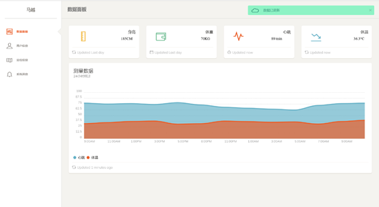
In the data viewing panel, users can view real-time heartbeat and body temperature measurement data and graphs of historical data.

Data viewing interface
In the personal information interface, users can update their personal information, bind family members, and view the data and location of family members.
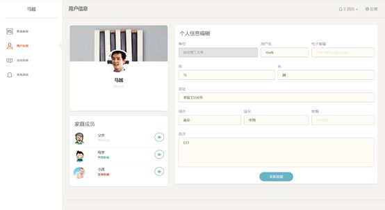
Personal information interface
At the same time, the system also provides viewing of positioning information, and the user can find the user's positioning information on this interface.
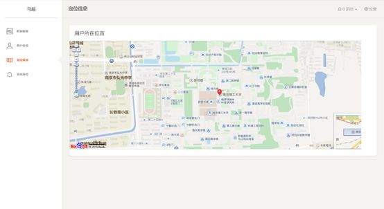
Map positioning interface
In the message prompt interface, the user can view the messages sent by the system. The system has a health warning function, and reminds the user's health data in four levels.
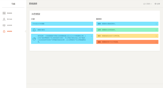
Message prompt interface
PC and APP
In the host computer interface, the user can view the real-time measurement curve graph; in the APP interface, the user can also view the measurement data.
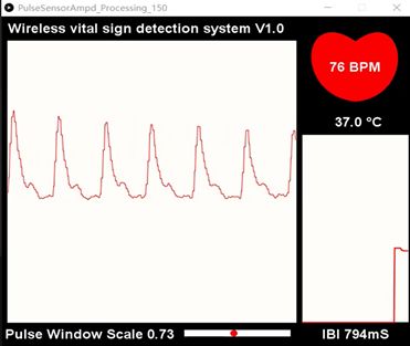
PC interface

Digital Display Test Pen ,Power Tester Pen,Voltage Pen,Digital Voltage Tester
YINTE TOOLS (NINGBO) CO., LTD , https://www.yinte-tools.com