This system is mainly applied to the detection of the amount of side slip of automobile wheels. In order to ensure the linear rolling of the car steering wheel without lateral slip, the wheel camber angle and the wheel toe are required to be properly matched. When the wheel toe value is not properly matched with the wheel camber angle, the wheel may not be purely rolling during straight running. A lateral slip phenomenon occurs. When this slip phenomenon is too serious, it will destroy the adhesion condition of the wheel, lose the directional driving ability, cause a traffic accident and cause abnormal wear of the tire. The magnitude and direction of the amount of lateral slip can be detected by the vehicle wheel side slip test rig.
This article refers to the address: http://
Side slide structure diagram: 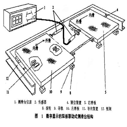
System hardware configuration:
2 displacement sensors
2 sets of photoelectric switches
Analog input module
Digital input module
How the system works:
When the wheel steps on the side slide, the first group of photoelectric switches is turned off (the photoelectric switch is normally open when it is not blocked), and when the side slide is left, the second group of photoelectric switches is turned off, and the side slip of the wheel is recorded at this time. Quantity, a set of wheel tests is completed. The wheels are stepped on the side slides in turn, and the side slip amount is recorded in the above manner to complete the side slip amount test of the entire vehicle.
Functional structure diagram:
System functions:
Vehicle positioning: The system provides three different vehicle positioning systems, namely single-bridge positioning, double-bridge positioning and multi-bridge positioning. Multi-bridge positioning needs to detect the amount of side slip of six sets of wheels.
System setting: You can set the upper and lower limit alarm value of the side slip amount, the length of the skateboard, and the trademark of the currently tested vehicle.
Customer Management: Ability to record and modify information on detected vehicles and support printing.
Function realization:
First, single bridge interface:
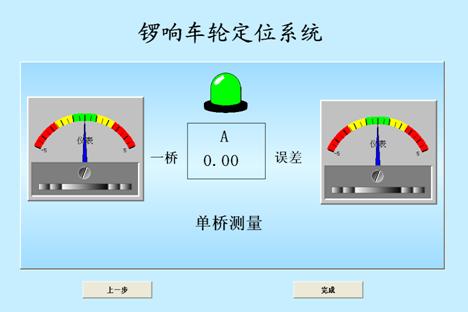
The two meters in the figure show the current amount of side slip, and display different scale backgrounds according to different value ranges. When a bridge error exceeds the set value, the alarm indicator light will change color.
Second, double bridge test
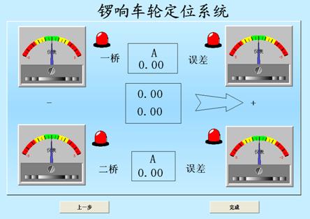
A meter that displays the amount of side slip is also provided. The alarm light flashes when the amount of side slip exceeds the set value.
Third, multi-bridge test
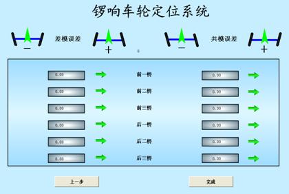
The differential mode error and common mode error of each group of wheels can be displayed, and the arrows on both sides are displayed according to different values, and the arrows display different colors in different numerical ranges. The amount of side slip for each set is automatically recorded as the process of detection. The process of manual recording has been omitted, providing the accuracy of the test.
Pneumatic Lifting Column,Telescopic Pillar Actuator,Telescopic Lifting Column,Telescopic Electric Cylinder
Kunshan Zeitech Mechanical & Electrical Technology Co., Ltd , https://www.zeithe.com