Method for driving insulated gate field effect transistor in Buck power supply
Author: Chang Hui Ya-ning CHEN Wei Jinling Wang Huabiao

I. Introduction
In the single-tube buck power supply shown in Figure 1, the topology is simple, but because the MOSFET source potential is not fixed, the drive is not easy. This paper analyzes and compares the different driving methods of the chopper power supply in terms of its circuit complexity, driving pulse quality, price cost, and adaptability of operating frequency.
Second, a variety of drive circuit analysis
1, level shift direct drive
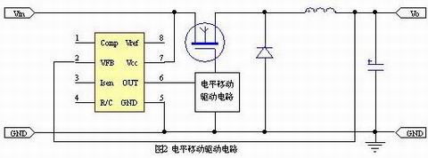
When the main circuit power supply voltage is not too high, you can insert the level conversion drive circuit shown in Figure 2. The advantage of this method is its low cost. The disadvantages are that when the input voltage Vin is high, it is not easy to handle it; second, the level shifting driving part needs the charge pump to supply power, so the circuit is complicated.
2, optocoupler isolation drive
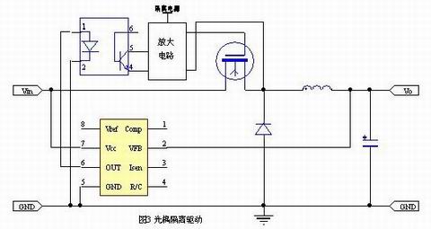
This is a common method. As shown in Figure 3, the advantage is that the circuit is relatively mature, but the optocoupler secondary needs to isolate the power supply. Because the speed of the optocoupler is not very fast, the operating frequency cannot be too high, and it may reduce the instantaneous power supply. State response speed.
3, change the MOSFET position, direct drive

As shown in Figure 4, the MOS tube is moved to the negative terminal of the power supply and can be directly driven by the signal output from the IC. The advantage is that the driving cost is low, and the disadvantages are that the output is suspended and the anti-interference performance is poor; second, the feedback cannot be directly introduced, and optocoupler isolation transmission is required.
4, transformer directly isolated drive

The obvious advantage of this direct drive method shown in Figure 5 is the lowest cost, but since the transformer can only deliver AC signals, the output positive and negative pulse amplitudes vary with duty cycle and apply only to a duty cycle of around 0.5. And it doesn't change much. At the same time, since the load of the transformer is the input capacitance of the MOS transistor, the front and rear edges of the driving pulse are generally not ideal.
5, active transformer drive
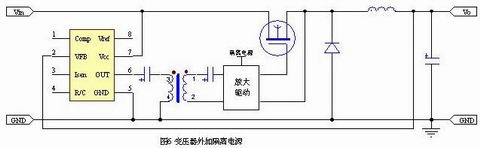
The transformer is used to transmit the signal, the secondary plus isolated power supply and amplifying circuit, as shown in Figure 6. Because the transformer only transmits signals, the response is relatively fast, the operating frequency can be very high, the secondary active, can output a relatively steep pulse signal. The disadvantage is that there is an isolated power supply.
6, using a new type of isolation drive components directly driven
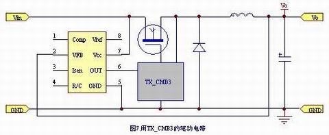
FIG. 7 shows a chopper circuit using a KD103 (formerly CMB3) type driver module, which is a single-tube isolation driver developed by Beijing Lamyuan Corporation. This driver uses transformer isolation and uses time-sharing technology to transmit PWM signals on the rising and falling edges of the input signal, delivering energy during the flat top stage, and thus capable of outputting steep driving pulses. The advantage of this driving method is that it is easy to use (when the MOSFET power is low, as long as the connection of Figure 7 is sufficient), the driving pulse quality is good, the operating frequency is high, the volume is small, the input voltage is up to 1000V, and the price is also relatively Cheaper. The disadvantage is that the transformers required at low operating frequencies are relatively bulky and at the same time slightly more costly, but the overall cost may be lower given the simplified design and reduced assembly costs.
Third, the conclusion
The following table summarizes the above analysis. It can be seen that, in most cases, the KD103 (formerly CMB3) dedicated chopper-isolated driver is the better choice.
Level shift driver
Optocoupler isolation driver
MOS transistor shift driver
Transformer direct drive
Active transformer drive
TX-KD module driverMaximum operating frequency
High or low, limited by the higher and higher optocoupler heightMinimum operating frequency
Can be very low or low, low, low, high, low, low, low, low, low pulse delay, large, basic, no delay, medium, very small,Drive design
Large, medium, and small, but the feedback design plus medium and small sizeAssembly workload
Medium, medium, and small Medium and small drives Part of the cost Low medium-low Low-medium medium Duty cycle Change range Large size comparison Large high-pressure work High is not easy High is not suitable Higher high High high