Audio and click and pop are bad noise from speakers or headphones. It is caused by a transient current pulse injected into the speaker coil, which instantaneously moves into and out of the speaker cone causing noise and breaks. Noise and broken noise can make people's ears feel unpleasant and bored. When the audio source is powered up or down, or when the audio signal is weakened or multiplexed by different loads, noise and breaks are generated. The transient pulses generated by these conditions are discharged through the speaker load, causing a bad noise and broken sound.
This article refers to the address: http://
Source of noise and broken sound
Some common causes of noise and break transients are: power transients; DC input transients; audio driver offset voltages.
Power supply transient
When the DC power of the audio component is turned "ON" (OFF), the voltage of the speaker or earphone may bounce due to the varying power supply voltage slew rate. Although power-by-pass capacitors help reduce noise spikes on a component's power supply pin, as shown in Figure 1, a technique built on the low-pass filter (LPF) of the V+ pin, The power pin transients can be further reduced.

A series resistor RSeries is placed between the IC's Vbattery supply pin and the V+ pin to form a low-pass filter (LPF) with a decoupling capacitor Cin. Since Intersil's audio switch IC consumes less than 10μA of supply current, this solution is very effective, and the voltage drop across the series resistor can be neglected when properly sized. This LPF converts the fast slew rate transient of the DC voltage to a slower exponential slope on the IC supply pin. The slower ramp voltage minimizes the switching transients of the power supply while eliminating all injected charge at the output of the switch, which can cause noise and breakage on the load.
2. DC input transients
Figure 2 shows a simplified layout of a single-supply audio amplifier that drives a 32Ω headphone, which is widely used in many portable media players. The audio amplifier's output signal is DC biased at half the system supply voltage, allowing full audio signal swing in both positive and negative directions. A 220μF DC blocking capacitor eliminates the DC offset of the headphone load. The 220μF capacitor and 32Ω load impedance form a high-pass filter (HPF) with a 22Hz corner frequency that covers the entire audio bandwidth.

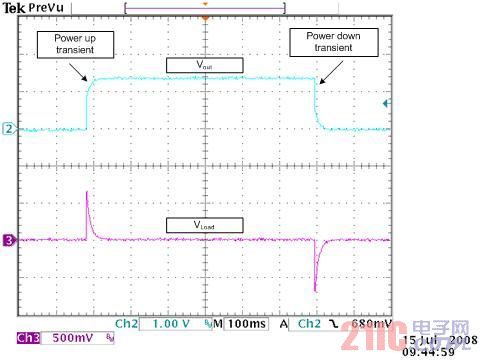
Figure 3 shows the transient voltage waveforms that appear on the headphones as the audio amplifier is powered up and down. When the audio amplifier is powered up (out of sleep mode) or powered down (in sleep mode), due to the dv/dt principle of the capacitor, an instantaneous voltage change occurs at the VLoad node of the capacitor. Since the load has a DC path to ground, the capacitor is discharged back to 0V. Sudden changes in DC voltage across the load can cause the speaker cone to move with transient pulse currents, causing noise and breaks.
3. Audio driver DC bias voltage
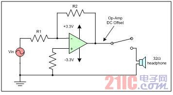
Figure 4 shows an application of an audio driver output stage that does not require a DC blocking capacitor because there is no DC offset voltage. This application typically uses a dual-supply audio driver with a negative swing capability or a single-supply audio driver. The audio driver's op amp (op-amp) can have a DC bias voltage ranging from ±10mV to ±20mV. Since the DC blocking capacitor is not used, this bias voltage is directly coupled to the speaker load when the switch is turned on (or decoupled when turned off). This offset voltage can be large enough to cause noise or breaks in the speaker.
Characterization of noise and broken sound
So far, the focus has been on the sources of noise and breaks. The waveforms for noise and break transients are given in this section. Characterizes the noise and break transients exhibited by various pre-amps, speakers, and headphones loaded in a normal (typical, ambient) listening environment. The speaker that completed the test was 6 inches from the listener's ear and had a properly applied earphone worn on the ear. The results below show that noise and breaks are the result of a load on the following common conditions:
For a 32W headset:
1. The pulse conversion rate exceeds 6.35V/s.
2. The pulse width exceeds 0.6μs.
3. The pulse amplitude exceeds 2mV.
For a 10 kW input impedance preamplifier, set a gain of 10 to drive the 4W speaker:
1. The pulse conversion rate exceeds 25V/s.
2. The pulse width exceeds 0.6μs.
3. The pulse amplitude exceeds 10mV.
For a 20 kW input impedance preamplifier, set a gain of 10 to drive the 8W speaker:
1. The pulse conversion rate exceeds 20V/s.
2. The pulse width exceeds 0.6μs.
3. The pulse amplitude exceeds 10mV.
By reducing the slew rate, width or amplitude of the transient pulses below the above threshold, noise and breaks can be reduced to an inaudible level. Intersil has developed a standard to eliminate noise and breaks in different loads. The standard is shown in Table 1. However, the audibility of noise and breaks is very subjective, depending on factors such as the sensitivity of the speaker, the sensitivity of the ear, and the amount of ambient noise in the listening environment. Therefore, Table 1 is only a guideline and does not mean that noise and breaks can be absolutely eliminated.
Table 1: Recommended conditions for eliminating noise and broken sounds
load | Gain | Pulse slew rate | Pulse duration | Pulse amplitude |
32 W headphones | Unit | ≤5V/s | ≤0.5μs | ≤1mV |
10k W preamplifier - 4 W speakers | 10 | ≤10V/s | ≤0.5μs | ≤5mV |
20k W preamplifier -8 W speaker | 10 | ≤10V/s | ≤0.5μs | ≤5mV |
It is important to note that when the pulse duration exceeds approximately 10 ms, "noise" or "breaking" occurs at each pulse transition (ie, rising or falling). For transient pulse widths ranging from 0.6μs to 10ms, the appearance of "noise" and "breaking" is so close that the appearance of sound is considered to be unanimous. As shown in Table 1, the reduction in pulse amplitude must eliminate noise and break, expressed as dB and based on the transient pulse amplitude of the 50% audio amplifier supply voltage bias, as shown in Table 2 below:
Table 2: Pulse amplitude reduction
voltage ( V ) | 32 W headphones ( dB ) | 10k W preamplifier – 4 W speaker ( dB ) | 20k W preamplifier - 8 W speaker ( dB ) |
1.8 | ≥ 65.1 | ≥51.1 | ≥51.1 |
2.5 | ≥68.0 | ≥54.0 | ≥54.0 |
3 | ≥69.5 | ≥55.6 | ≥55.6 |
5 | ≥74.0 | ≥60.0 | ≥60.0 |
Intersil reduces noise and breaks
Intersil uses different technologies in the Switch/MUX product line to eliminate noise and breaks. The choice of which technology to use is determined by a necessary DC blocking capacitor. The following section describes two techniques implemented with Intersil's analog switches.
1. Noise and broken shunt network
The single supply negative signal swing design is capable of simulating the switch, allowing the audio input signal to reach below ground. One benefit of this design is that the DC blocking capacitor can be placed between the audio driver and the switch, not between the switch and the load. The ground-to-ground low-impedance shunt resistor with this configuration can be integrated into the switch to discharge the DC-blocking capacitor when the audio driver is turned on or off. For example, when entering the power-on state from the off state, the SPDT switch adopts the configuration shown in FIG. When the audio driver supply voltage appears, the shunt resistor discharges and the switch input node returns to ground. Assuming a suitable RC time delay discharges the switch input to 0V, the switch can be connected to a 32W load without noise and break transients.
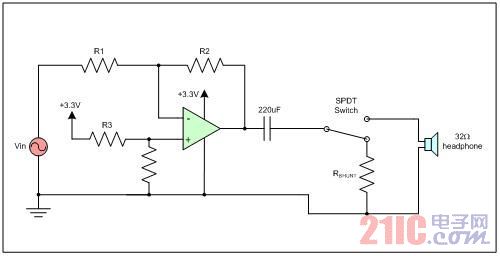
Figure 5: Analog switch with shunt network (figure: SPDT switch, 32W headphone)
Figure 6 shows the input and output waveforms of the ISL54406 with noise and broken shunt circuit disable. When the audio driver is turned on, the transient voltage across the DC blocking capacitors at both ends is directly coupled to the switching output. It can be seen that the speaker is DC-discharged at the switch input, causing noise and breaks.
The noise and breakover shunt circuit in Figure 7 uses the ISL54406. The 100ms delay time fully discharges the switch input to 0V before the switch is turned on to connect the audio driver to the speaker load. When the switch is turned on after a time delay, it can be seen that the transient voltage on the load is negligible, eliminating noise and breaks. 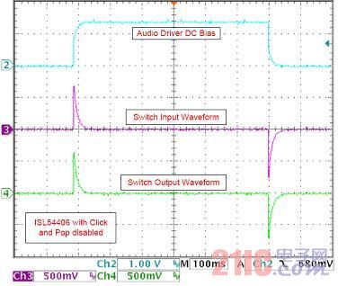
Figure 6: ISL54406 with noise and break enable function
(Picture word: audio driver DC bias, switch input waveform, switch output waveform, ISL54406 with noise and break enable function) 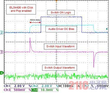
Figure 7: ISL54406 with noise and broken sound
(Picture word: ISL54406 has noise and broken sound function, 100ms delay, switching logic, audio driver DC bias, switch input waveform, switch output waveform)
2. Soft start switch
In portable applications, reducing the size is a top priority, and a single-supply audio driver that swings below ground potential can be used to eliminate DC blocking capacitors. Audio drivers that do not require DC blocking capacitors are still subject to noise and breakage issues because the audio driver op amps have a DC offset voltage range of ±10mV to ±20mV. If there is no capacitor to eliminate the DC offset voltage, the switch will couple the offset to the load when the switch is switched.
The solution to this problem is to gradually increase the switch OFF resistance to the switch ON resistance so that the load voltage conversion rate (V/s) is slow enough to not cause noise and break. The soft start switch can progressively reduce the switch resistance when the switch is turned on by the modulation switch on time. A progressive change in resistance establishes a time varying voltage divider on the load when the power is turned on. On the load, the satisfactory slew rate given in Table 1 can eliminate noise and breakage due to the DC offset voltage.
Figure 8 highlights the ISL54405 device with integrated soft-start switch. An external soft-start capacitor can be used to change the switch-on time and limit the switch output slew rate. Figure 9 and Figure 10 show the ISL54405 device with soft-start disable. Using the 20mV DC signal at the input of the switch, the switch is turned on to produce an output that boosts the slew rate to more than 1000V/s. Figure 11 shows the ISL54405 device with soft-start on. With the soft start function, the switching output of the switch output is now less than 5V/s, which is in line with the noise and break elimination standards, as shown in Table 1. 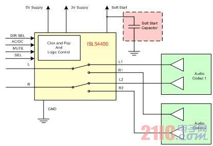
Figure 8: ISL54405 device with soft-start capacitor (figure: 5V supply, 3V supply, soft start, soft-start capacitor, noise and break and logic control, audio codec 1, audio codec 2) 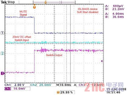
Figure 9: ISL54405 with soft-start disable feature (Part 1)
(Picture word: MUTE signal, 20mV offset switch input, switch output, ISL54405 device soft start disable) 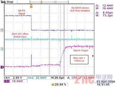
Figure 10: ISL54405 for soft start and disable functions (Part 2)
(Picture word: MUTE signal, 20mV offset switch input, switch output, ISL54405 device soft start disable, conversion rate = 1550V/μs) 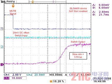
Figure 11: ISL54405 with soft start enable
(Picture word: MUTE signal, 20mV offset switch input, switch output, ISL54405 device soft start, conversion rate = 3.5V/μs)
in conclusion
Noise and broken sound can have an adverse effect on audio applications, and there are techniques to eliminate this transient. If the characteristics of noise and break transients are reduced, noise and breaks can be eliminated, so that the criteria given in Table 1 can be met. The introduction of Intersil analog switches with integrated noise and break cancellation enables high-performance audio signal routing while minimizing board space and power consumption.
The compact FujiFilm Instax Mini 8 Camera preserves the ease of use and attractive design elements of the existing Instax Mini series. At the same time, the Mini 8 cameras offer new features and enhancements. You will instantly notice a slimmer and lighter body. The Instax Mini 8 is approximately 10 percent smaller than the Mini 7S in volume ratio. It is now even easier for the consumer to carry around an INSTAX with them everywhere. The Fujifilm Instax Mini 8 Camera features automatic exposure measurement. The camera signals the recommended aperture setting with a flashing LED light and the user can manually adjust the dial to the recommended setting. This helps the user capture the perfect photo every time. A High-Key mode is available on the Instax Mini 8 cameras. This mode enables consumers to take brighter pictures with a soft look - perfect for portraits. The viewfinder has also been improved for enhanced subject viewing.
Instax Mini 8
Instax Mini 8,Instax Mini 8 Camera,Instant Camera Mini 8,Instax Mini 8 Pink
GuangZhou CAIUL Digital Products CO,.LTD. , https://www.caiul-instax.com