The classroom is the main part of school lighting. The classroom light illuminance design standard is the indoor average illumination of 300 lx, so the high illumination requirement, if there is no reasonable control scheme, the energy will cause huge waste. Therefore, the application of intelligent lighting control system to ordinary classrooms and lecture halls has considerable practical significance. For the school, the use of dimming control method is obviously too expensive and difficult to accept, and most of the lamps in the teaching building have chosen fluorescent lamps. The dimming control requires a dedicated dimming ballast, which is rather cumbersome. Therefore, switch control is the main control method for school classroom lighting. This paper combines the actual circuit of the school, uses the power line communication, and adopts the PLCBUS protocol to design a low-cost intelligent lighting control system for the unified control lights of the classrooms in the teaching building.
Intelligent lighting system design
The intelligent lighting system design is divided into three parts: the main control module, the slave control module and the illuminance sensor module. The slave control module can set multiple addresses, and the master control module and the sensor module issue address control commands, and the receiver module with the same address responds according to the command to turn the light on or off. By grouping the addresses of the receiving modules, it is possible to control the lighting and sub-areas of all classrooms. The PC and controller can also issue a user on or off command to turn all classroom lights of the same user code on or off.
Receiving module circuit
The receiving module circuit designed by PLCBUS-9402393 chip is shown in Figure 6. A receiving module can control two lighting circuits, which are controlled by pins 12 and 13 of the chip. Each loop can be set with one primary address and 15 secondary addresses. The 19 and 22 pins of the receiving module are connected to the power line, and the command is received from the power line. The chip determines whether the destination address in the instruction is the same as the address of the module in the instruction after receiving an instruction from the module. Similarly, according to the instruction code, the chip 12 or 13 pin outputs a high level, and the Q1 and Q2 transistors 9014 amplify the current. When the current increases to the signal relay OJT-SS-112LM operating current, the relay coil is turned on, then K1 Or K2 is closed, the lighting circuit LOAD1 or LOAD2 is turned on, and the light is turned on. If there is no high level output according to the instruction chip 12 and 13 pins or the output value is less than the signal relay action current, the corresponding lighting circuit is turned off and the light is turned off. After receiving the control command, the receiving module will send feedback information to the control module. The wall switch can be installed after the receiving module. Only after the module is powered, can the wall switch be used to turn on the light, which can save energy.
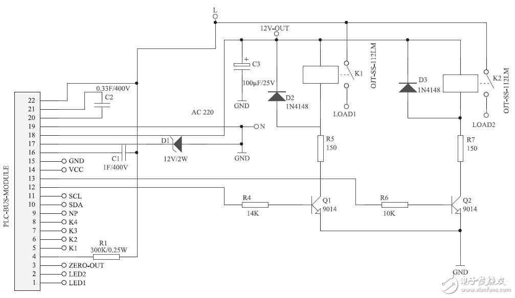
Figure 6 Receiver module lighting control circuit
Control module circuit
The 5, 6, 7, and 8 pins of the chip are connected to four buttons K1, and the control module circuit is shown in Figure 7. K1, K2, K3, K4, each button can be sent with different address control commands by presetting the chip. For example, when the K1 trigger is set, the chip sends a B1 on command to the power line. When the button K1 is pressed, the module sends The B_ command, the switch of the corresponding lighting circuit of the receiving module with address B1 will be closed and the light will be turned on. When the K2 trigger is set, the chip sends a B1 off command to the power line. When the button K2 is pressed, the module sends a B1 off command, and the corresponding lighting circuit switch of the receiving module with the address B1 is turned on, and the light is turned off. The 10 and 1 pins of the chip are connected to the PC or MCU for communication, and the control command and the module chip setting function can be completed.
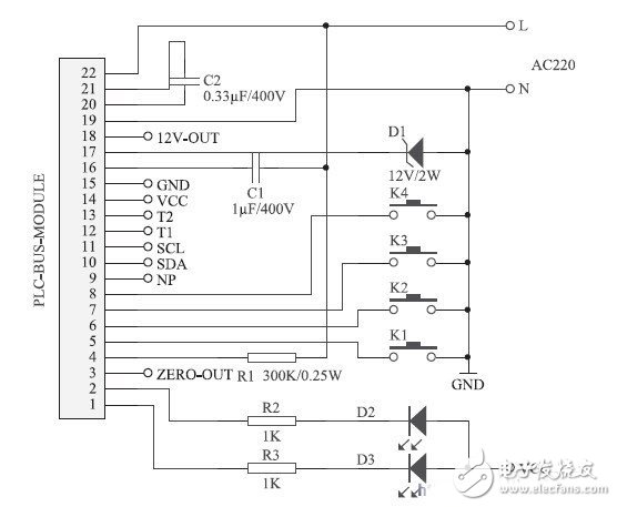
Figure 7 control module circuit
  
Capacitor For Power Transmission And Transformation
Capacitor for power transmission and transformation
New Parallel Capacitor 100Kvar,Capacitor Banks,High Voltage Capacitor Banks,Parallel Capacitor 200kar
YANGZHOU POSITIONING TECH CO., LTD. , https://www.cnpositioning.com