Due to the development of digital technology and computer technology, traditional analog switches have been replaced by program-controlled digital switches, which are an integral part of digital switches. This article is to use the MT9075 chip produced by Mitel to realize the function of the digital trunk interface.
1, MT9075 chip introduction [1]The MT9075 is a device from Mitel that can generate and process PCM30 signals. It combines PCM30 framer, linear interface unit (UU) and link controller with clock synchronization, interrupt control, synchronization and error protection. CAS signaling, CCS signaling processing, signal echo and other functions. Through the parallel microprocessor interface provided by MT9075, the main CPU can read and write control and interrupt receiving processing of its status word, which can easily realize the control and processing of line signaling. Using the MT9075 to implement the digital trunk interface can reduce the burden on the CPU and simplify the design of the system hardware and software.
In this paper, ARM chip S3C44B0 is used as the main control CPU to complete the control of the whole system; MT8980 is used as the core device of the digital switching network part; MT9075 is used as the core device of the digital relay interface. Figure 1 shows the specific circuit of the digital trunk interface. The circuit design is to design the necessary peripheral circuits according to the chip requirements. The MT9075 has three main ports:
1) Line interface, the transmitted code stream is 2.048M bit/s bipolar HDB3 code, with the frame structure of PCM30/32 system, used to connect PCM30/32 base group line. [2] It is connected to external trunk by external transmitting and receiving transformers, wherein TX1 and TX2 are line transmitting ends, and a 1:2 transmitting transformer is connected via an impedance matching circuit; RX1 and RX2 are line receiving ends, and an impedance is obtained. The matching circuit is connected to a 1:1 receiving transformer.
2) ST-BUS interface, the transmitted code stream is 2.048M bit/s unipolar code, and the code stream has the frame structure of PCM30/32 system, wherein DSTI connects the output channel STO of digital switching chip MT8980, DSTo connects MT8980 Input channel STI.
3) Processor interface, A0~A5, DO~D7, CS, R/W, etc. The interface between the MT9075 and the processor can be connected in two ways: INT or MOT, where INT is used. The address lines A0~A4 and DO~D7 of the MT9075 are directly connected to the corresponding address lines and data lines of the S3C44B0, and occupy an address space as an external expansion device of the S3C44B0. The S3C44B0 controls the MT9075 through the chip select signals NGCS5 and /RD, /WR read and write signals. [3]
In addition, the MT9075 can automatically monitor various synchronization states, such as bit synchronization, basic frame synchronization, CRC-4 multi-frame synchronization, and remote multi-frame synchronization. Regardless of the loss of any of these types of synchronization, normal communication cannot be completed. To stabilize the communication, the 20MHz timing signal of the MT9075 and the system clock C4b (4.096 MHz) and the basic frame synchronization signal Fob (8 kHz) are used. The high-stability clock generator is directly provided, and the MT9075 can automatically divide the 64 kHz internal clock and the 2.048 MHz bit-synchronous clock E2o from these signals using an internal digital phase-locked loop.
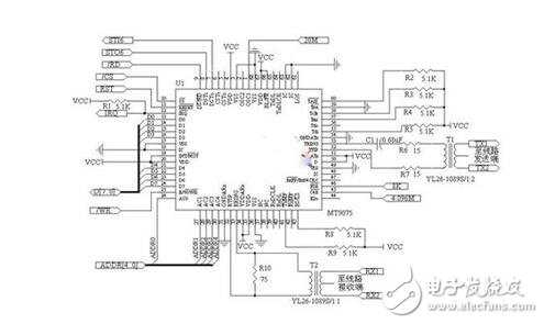
Figure 1 MT9075 circuit diagram
3, software part designThe software introduces the read and write control, initialization processing and digital relay processing program of MT9075. The address assigned by MT9075 is a part of the address of NGCS5 of S3C44B0, and its base address is 0a000000, which is defined as follows:
#define MT9075_Page (*(volaTIle unsigned char *) 0x0a000000)
The address of the control word of the page class is 0a000010~0a00001f respectively. For example, the address of MulTIframe, National Bit Buffer and Data Link Selection Word and Mode Selection Control Word under Page 01H are 0a000010 and 0a000011, respectively, as follows:
#define MT9075_ADDR0 (*(volatile unsigned char *) 0x0a000010)
#define MT9075_ADDR1 (*(volatile unsigned char *) 0x0a000011)
3.1 Read and write control of MT9075
The read and write control of the MT9075 is mainly divided into two steps: the first step selects the control word page number to be read and written, and the second step performs read and write control operations on the control word in the page. For a soft reset of the MT9075, the code looks like this:
MT9075_Page = 0x01; //Select Page 01H (Master Control 1)
MT9075_ADDR1 = 0x20; //Write the control word Mode Selection Control Word(11H)// under Page 01H to set MT9075 software reset, write control word 0x20
3.2 Initialization of MT9075
The MT9075 needs to be initialized when the system is powered on, including MT9075 software reset, interrupt processing, CAS mode selection, impedance mode setting, JA mode setting, DSTo output enable, and transmission signal settings.
In order to make the code concise, a function is used to replace the above two steps of the MT9075 read and write control, the function is as follows:
Control_9075 (PageNo, RegAddr, Wdata)
{ MT9075_Page = PageNo;
RegAddr = Wdata; }
The initialization code for MT9075 is as follows:
Control_9075 (0x01, MT9075_Addr1, 0x20);
Control_9075 (0x01, MT9075_Addr11, 0xff);
Control_9075 (0x01, MT9075_Addr10, 0xc8);
Control_9075 (0x01, MT9075_Addr1, 0x82);
Control_9075 (0x01, MT9075_Addr15, 0x02);
Control_9075 (0x02, MT9075_Addr8, 0xa0);
Control_9075 (0x02, MT9075_Addr3, 0x04);
Control_9075 (0x01, MT9075_Addr10, 0x8c);
Control_9075 (0x01, MT9075_Addr2, 0x9f);
Control_9075 (0x05, MT9075_Addr1, 0xff);
Control_9075 (0x05, MT9075_Addr2, 0xff);
. . . . . . . . . . . .
Control_9075 (0x05, MT9075_Addr15, 0xff);
When the CPU needs to send the line signaling of the voice channel, it can operate through the related register of Page 05H (Transmit Channel Associated Signalling Page). At the end of the initialization, the control word in Page 05H is operated, and ff is written to MT9075_Addr1 to MT9075_Addr15, so that the output channel DSTo is outputted to a high level after power-on, and the writing of ff to MT9075_Addr3 to MT9075_Addr14 is omitted. Line code.
3.3 Digital Relay Processing Program
In the implementation process, the signaling part is a simple protocol designed by itself, not standard E1 signaling. The signaling is transmitted in the 16th time slot of DSTo and DSTi, and the synchronization signaling is transmitted in the 0th time slot. The signaling of the calling party is transmitted to the called relay through the interface line, and is stored in the register of the called party MT9075. The called party CPU performs the corresponding operation by reading the signaling content in the register, and the called party signaling arrives at the calling party and the process is reversed. 2 is a schematic diagram of a user calling another user through a digital trunk. This figure assumes that the called party is not busy. If the called party is busy at any time during this process, the called busy information is sent to the calling party, and the calling party closes the opened channel to wait for the next call. Figure 3 is a basic flow chart of the digital relay processing program.
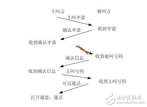
Figure 2 Schematic diagram of digital trunk call
4 ConclusionThe hardware and software of the continuation interface circuit in the digital design using the above scheme have been debugged and passed, and the work is stable, which can satisfy the normal use of the user. With the single-chip MT9075, 30 pairs of users can be exchanged at the same time. Considering that the user is not talking at the same time, it is very convenient to realize more user exchange work.
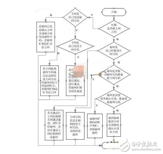
Figure 3 Basic flow chart of the digital relay processing program
O Ring,sealing ring,silicon seal
Chongqing LDJM Engine Parts Center , https://www.ckcummins.com