At present, 115V/400 Hz power supplies are widely used in military equipment such as aviation and aerospace. Military equipment generally requires high frequency accuracy, so it must be tested to meet military standards. This design utilizes the powerful processing capability of the digital signal processor (DSP) for digital signals, and tests, analyzes and calculates the AC voltage and frequency to achieve the purpose of evaluating the performance of the intermediate frequency power supply.
  1 system hardware design
   1 . 1 system hardware block diagram
The hardware block diagram of the system consists of four parts: voltage signal conditioning module, frequency signal conditioning module, DSP2407 minimum system and liquid crystal display module. The system hardware block diagram is shown in Figure 1. The measured signal (voltage signal) is step-filtered by the signal conditioning module, and then connected to the ADCIN00 terminal of the DSP for signal acquisition and A/D conversion, and the measured signal (frequency signal) is stepped down, filtered, and converted into a signal conditioning module. After the same frequency square wave, it is connected to the CAP end of the DSP for capture. DSP2407 is the core of the whole system. Its function is to receive the signals of A/D and capture CAP, analyze and calculate it, and finally store and display the data.

1 . 2 signal conditioning module
The signal voltage to be measured is -115 to 115V, and the input requirement of the DSP is 0 to 3.3 V. Therefore, the voltage signal to be measured needs to be conditioned. After the measured voltage signal is processed by step-down, filtering, etc., it can enter the DSP for A/D conversion. The voltage signal conditioning circuit is shown in Figure 2.
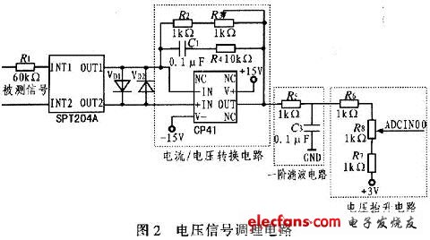
The voltage sensor in Figure 2 is a precision voltage transformer SPT204A with an input current rating of 2 mA and a rated output current of 2 mA. The input of the voltage transformer needs to adjust R1 to make the input current 2 mA, and the output of the transformer is the current/voltage conversion circuit, and the feedback resistors R2 and R3 can be adjusted to obtain the required voltage. Two reverse-connected diodes function as protection amplifiers. The transformer is characterized by electromagnetic isolation, high precision, no drift, and has a good inhibitory effect on interference. The filtering part is a first-order low-pass filter, which aims to eliminate high-frequency signals that have a great influence on the system. After the signal under test is conditioned by the voltage transformer, it is converted into a voltage signal of -3 to 3 V, and the A/D converter of the DSP2407 is unipolar. Therefore, the voltage rise circuit is connected to the transformer circuit to further adjust. The voltage signal is converted into a voltage signal of 0 to 3 V, and then A/D conversion is performed.
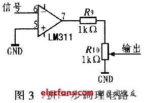
The step-down filter part of the frequency signal conditioning module is basically the same as the voltage signal conditioning circuit, except that the voltage signal is not required to be raised, but the sinusoidal voltage signal is converted into a square wave signal of the same frequency through the voltage comparator LM311, and finally the minute is passed. The voltage circuit further adjusts the amplitude to fit the input range of the DSP capture terminal. Further conditioning circuit is shown in Figure 3.
1 . 3 liquid crystal display
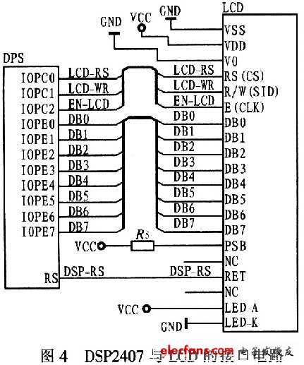
Liquid crystal display (LCD) is a key device that provides a friendly human-machine interface for information human-computer interaction. Because LCD has the advantages of low power consumption, small size, light weight and many other displays, it becomes an important tool for measurement results display and human-machine dialogue. The SPRT12864M liquid crystal display module selected by this system is a 128&TImes; 64 dot matrix graphic dot matrix liquid crystal display module.
The interface circuit between DSP2407 and LED is shown as in Fig. 4. The IOPE0~IOPE7 of the DSP is used as the data interface, and is connected with the data lines DB0~DB7 of the LCD module to complete the data transfer with the LCD; the IOPC0 is connected to the RS (CS), the command/data selection bit, and H is the data selection bit. L is the instruction selection bit; IOPC1 is connected to the R/W pin, is the read/write select bit, H is the write signal, L is the read signal; IOPC2 is connected to E, the working state is enabled; RET is the reset end of the liquid crystal display module It is directly connected to the reset pin RS of the DSP. When the system is reset, the LCD is reset at the same time; VDD is connected to +3.3 V input power.
2 system software design
DSP is the core of the entire test system, and software programming is the core of this core. The entire DSP system is developed in the Code Composer Setup compilation environment, and the programming of the assembly system and the C language is used to complete the software design of the entire test system.
2 . 1 voltage data acquisition subroutine
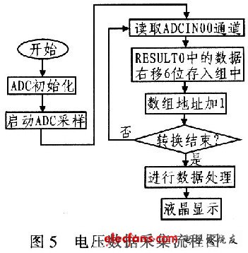
Voltage data acquisition is directly implemented by the analog-to-digital conversion module (ADC) that comes with the TMS320LF2407. First, the ADC is initialized to determine the cascade mode of the ADC channel, the sampling time window is pre-defined, and the conversion clock is pre-defined. Then start ADC sampling, collect the voltage signal, and sample it 8 times. Since the obtained data is stored by default into the upper 10 bits of the ADC conversion result register (RES-ULT0~7), an array is defined, and the value in RESULT n is shifted and restored to the corresponding array. After the A/D conversion is completed, it is transferred to the interrupt service routine to analyze and process the sampled data. The flow chart of the voltage signal data acquisition subroutine is shown in Figure 5.
2 . 2 frequency data acquisition subroutine
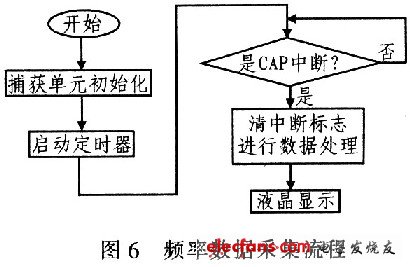
The AC voltage frequency is captured by the capture pin of DSP2407, and the clock of the rising edge of the square wave output of the frequency signal conditioning module is captured. Then, the data processing part of the frequency acquisition signal is obtained according to the adjacent clock difference. Frequency value. The frequency signal data acquisition subroutine flow is shown in Figure 6.
3 Conclusion
The system is based on the design of DSP-based IF power supply test system. The test system with DSP as the control core is built. The peripheral circuit of voltage transformer SPT204A is designed and improved. The AC voltage output and the required input are established. The platform proposes a new idea of ​​voltage signal conditioning, which has the advantages of simple structure and good performance, and can be popularized into system testing of other intermediate frequency military equipment and civil equipment.
The efficiency of radiator determine the performance of water cooling system directly, aluminum not only has excellent heat dissipation, but also has the smaller density,
aluminum radiator lighter than the same volume of copper radiator. The heat dissipation performance of radiator mainly depends on two aspects, one is the thickness, the other is the spacing of fins. The FPI (Fin Per Inch) value is used as a reference. And the matching of the fan is also very important.
Pure Aluminum Radiator,Aluminium Radiator,Aluminum Heating Radiators,Aluminum Cooling Radiators
Dongyuan Syscooling Technology Co., Ltd. , https://www.syscooling.com