Field programmable gate arrays, or FPGAs, are further developed based on programmable devices such as EPLD, PAL, and GAL. As an semi-custom circuit in the field of professional integrated circuits, FPGAs not only solve the shortcomings of custom circuits, but also overcome the shortcomings of the original programmable devices due to the limited number of gates. The use of FPGAs is very flexible, and the same FPGA can achieve different circuit functions by using different programs. FPGAs are now widely used in communications, instrumentation, networking, data processing, industrial control, military, and aerospace. With the further reduction in cost and power consumption, FPGAs will be used in more fields.
TOP1 Interpretation of FPGA Programmable Filter System Circuit
A filter is a device used to eliminate interfering noise and can be used to effectively filter out frequencies at a particular frequency or frequencies outside of that frequency. It occupies a very important position in the electronics field and has been widely used in signal processing, anti-interference processing, power systems, and anti-aliasing processing. For the programmable filter, the biggest feature of the system is that its filtering mode can be selected by program control, and the -3 dB cutoff frequency is programmable, which is equivalent to a multi-function filter, which will have better application prospects. In addition, the system has the function of amplitude-frequency characteristic test, and displays the spectral characteristics through an oscilloscope, which can intuitively reflect the filtering effect.
Amplification module
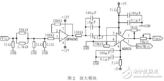
The specific circuit of the amplification module is shown in Figure 2. The first part is a voltage divider network, in which the first four resistors attenuate the input signal by a factor of 100 and form a 51Ω impedance with the signal source internal resistance. The latter 51Ω is the matching resistor. The second part uses the OPA690 to amplify the small signal by a factor of two, while acting as an impedance transform and isolation. Since the input impedance of the AD603 is 100Ω, a 100 Ω resistor is connected in series to match. The third part is the AD603 variable gain amplifier, whose gain increases linearly in dB as the control voltage increases. The reference voltage of the 1 pin is obtained by the operation of the microcontroller and controlling the output voltage of the DAC chip, thereby achieving accurate numerical control. Gain G(dB)=40VG+G0, where VG is the differential input voltage, the range is -500~500mV; G0 is the gain start point, which is different when connected to different feedback networks. Indirectly, a 5kΩ potentiometer is changed in the 5th and 7th pins.
High-pass filter module
The LTC1068 is a low noise, high precision general purpose filter that, when used for high pass filtering, has a cutoff frequency range of 1 Hz to 50 kHz and no aliasing up to 200 times the cutoff frequency. Since the four channels of the LTC1068 are low-noise, high-precision, high-performance 2nd-order filters, low-pass, high-pass, band-pass, and band-stop filters can be implemented with only a few external resistors per channel. The specific circuit is shown in Figure 3. The B port Q value is 0.57, and the A port Q value is about 1. In the debugging of the circuit, it is found that the Q value of port A needs to be larger than the value of port B, otherwise the amplitude of the signal at the cutoff frequency will be up.
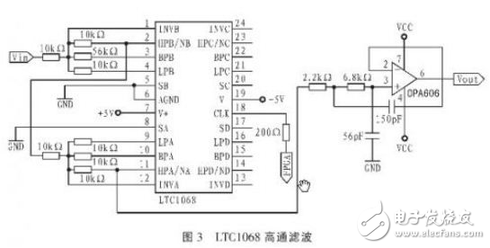
The LTC1068 has a clock frequency to passband ratio of 200:1. Since the LTC1068 internally doubles the clock signal CLK, when the cutoff frequency is at least 1 kHz, the internal clock frequency is actually 400kHz, so add a cutoff after the LTC1068. A low-pass filter with a frequency of 450 kHz filters out noise and higher harmonics in the sub-band.
Low pass filter module
Implement a low-pass filter with the MAX297. The switched capacitor filter MAX297 can be configured as an 8th order low-pass elliptical filter with a stopband attenuation of -80dB and a 50:1 ratio of clock frequency to passband frequency. By changing the frequency of CLK, the filter -3 dB cutoff frequency can be adjusted from 1 to 20 kHz, stepping 1 kHz.
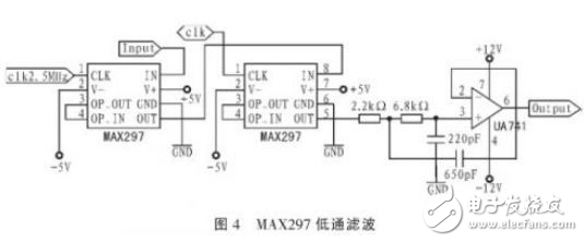
When using the MAX297, it should be noted that when the signal frequency and the sampling resolution are the same frequency, the switched capacitor group picks up the same amplitude signal amplitude signal on the capacitor, which is equivalent to the input signal is DC, so that the filter The device outputs a DC level. Similarly, the same phenomenon occurs when the signal frequency is an integer multiple of the sampling frequency. To this end, in front of it, an analog low-pass filter is added to effectively exclude high-frequency signals of the sampling frequency and above. Therefore, with the first-level MAX297, the cutoff frequency is set to 50kHz. The clock frequency is set to 2.5 MHz. Behind it, a low-pass filter is also added, with a cutoff frequency of 150 kHz to filter out the high-frequency components of the signal to make the waveform smoother. The specific circuit is shown in Figure 4.
Fourth-order elliptical low-pass module
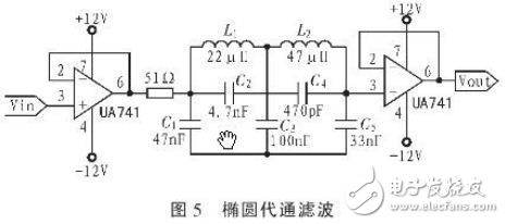
The system requires a fourth-order elliptical low-pass filter with in-band undulations of ≤1 dB and a -3 dB passband of 50 kHz, using a passive LC elliptical low-pass filter. Simulate the simulation filter with Filter Sol uTIon, then simulate the simulation in MulTIsim and adjust the parameters of the capacitor and inductor to their nominal values. In addition, the emitter follower is used before and after the elliptical filter to avoid front and rear stage effects. The specific circuit is shown in Figure 5.
----------------------------------------
Paperlike Screen Protector For IPad
Paperlike Screen Protector,iPad Paperlike Screen Protector,Paperlike Screen Protector iPad
Shenzhen Jianjiantong Technology Co., Ltd. , https://www.jjtscreenprotector.com