Three-dimensional (3D) scanning is a powerful tool that can acquire a variety of volume data for measurement equipment, inspection equipment, detection equipment, and 3D imaging equipment. When designers need to perform fast and high-precision scanning with millimeter to micrometer resolution, they often choose structured light systems based on TI DLP technology.
The birth of the 3D scanning systemSimple two-dimensional (2D) inspection systems have been around for many years. Their working mechanism is usually to illuminate an object and take a picture, and then compare the taken image with a known standard 2D reference. 3D scanning increases the ability to obtain volume information. The introduction of z-dimensional data can measure the volume, flatness or roughness of an object. For industries such as printed circuit board (PCB), solder paste, and machined parts inspection, it is essential to measure the above-mentioned additional geometric structural features, which cannot be achieved by 2D inspection systems. In addition, 3D scanning can also be used in industries such as medical, dental, and hearing aid manufacturing.
Coordinate measuring machine (CMM) is one of the first industrial solutions to collect 3D information.
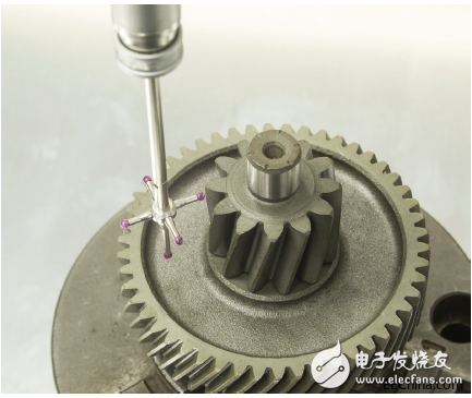
Figure 1. Example of a coordinate measuring machine probe
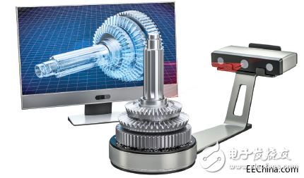
Figure 2. Optical 3D scanning using structured light
The probe physically touches the surface of the object and combines the position data of each point to create a 3D surface model (Figure 1). Later, optical methods for 3D scanning appeared, such as structured light (Figure 2). Structured light is the process of projecting a set of patterns onto an object and capturing the distortion of the pattern with a camera or sensor. Then use the triangulation method to calculate the data and output a 3D point cloud, thereby generating data for various calculations in the measurement, inspection, inspection, modeling, or machine vision system. The reason why optical 3D scanning is favored is that it does not touch the object under test and can obtain data very quickly or even in real time.
DLP technology can quickly and intelligently generate light imagesFor optical 3D scanning equipment, DLP technology is usually used in the system to generate structured light. The DLP chip is a highly reflective aluminum micromirror array called a digital micromirror device (DMD).
When the DMD is combined with the illumination light source and optical devices, this sophisticated micro-electromechanical system (MEMS) can provide assistance for various projection systems and spatial light modulation systems.
Because DMD can generate various structured light patterns flexibly, quickly, and highly programmable, designers often use DLP technology for structured light applications. Unlike a laser line scanner or a diffractive optical element (DOE) with a fixed pattern set, it can program multiple patterns with different bit depths to a DMD. Structured light solutions based on DLP technology are very suitable for detailed measurements that require millimeter or even micron accuracy.
3D scanning system application 3D AOI3D Automated Optical Inspection (AOI) is a powerful technology used in manufacturing environments that can provide real-time, online, and decisive measurement data related to part quality. For example, 3D measurement is very suitable for PCB solder paste inspection (SPI) because it measures the actual volume of solder paste deposited before component placement, helping to prevent poor quality solder joints (Figure 3). In PCB manufacturing, online 3D AOI will also be performed after component placement, reflow soldering, final inspection and rework operations to maximize quality and reliability. With the increasing popularity of 3D inspection functions, more and more online factory inspection points choose to use 3D AOI systems.
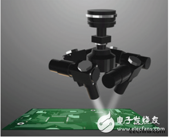
Figure 3. PCB 3D SPI example
Medical treatmentThe application of 3D scanning technology in the medical industry is growing rapidly. For example, in dentistry, an intraoral scanner (IOS) is used to directly collect optical impressions (Figure 4). In the production of prosthetic restorations, such as inlays, onlays, copings and crowns, 3D image accuracy at the micron level is required. IOS simplifies the dentist's clinical procedures, eliminates the need for plaster models and reduces patient discomfort.
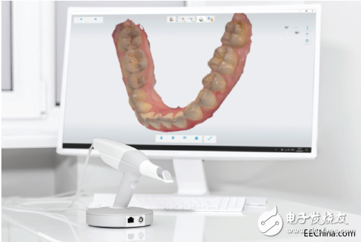
Figure 4. Dental intraoral scanner
Another fast-growing application industry is 3D ear scanning. The optical imaging system can accurately collect the 3D model of the ear without using silicone ear impressions. 3D ear scanning can also be used to customize earplugs, hearing aids and hearing protection devices for consumers in the future.
Industrial Metrology and InspectionMany different industrial metrology and inspection systems have begun to use 3D optical scanning technology.
Optical 3D surface inspection microscopes are an alternative to offline CMM systems. This type of microscope can measure more features about height, roughness, and computer-aided design (CAD) data comparison. In addition, factories that produce machined, cast or stamped products are another major application area for optical inspection.
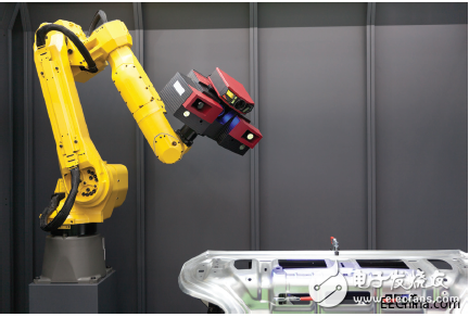
Figure 5. Robot arm with 3D scanner
They can more easily and accurately measure the three-axis directions of X, Y, and Z, thereby improving quality assurance. A solution combining an online 3D vision system and a robot arm has also appeared on the market (Figure 5). Using these robotic solutions can greatly improve the speed and quality of cars (Figure 6) and other production line factories. Adding 3D inspections at specific stages in the assembly and production process helps to detect quality problems early, thereby reducing waste and rework. The 3D scanning system can even be used in computer numerical control (CNC) equipment and 3D printers, enabling real-time measurement during the manufacturing process.

Figure 6.3 Application of D structured light scanning in vehicle positioning detection
Professional 3D handheld scannerThe professional 3D handheld scanner is a portable tool for professionals and amateurs to collect the complete details of real objects in a 3D data format (Figure 7).
The collected data can be used for product design, parts engineering, 3D content creation or as input information for a 3D printer. For example, online retailers can use 3D scans of their products to present products online in real, high-quality 3D models instead of 2D pictures. Game players can scan themselves in 3D and create their own characters in the game.
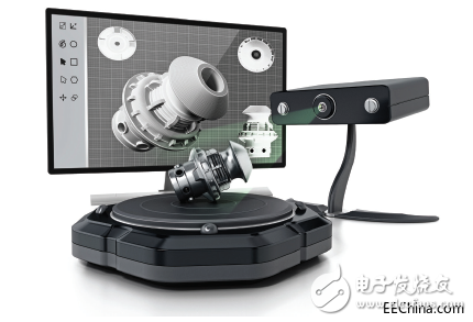
Figure 7. Desktop professional 3D scanner
3D biometrics and identity verification3D scanning continues to evolve in the application of biometrics and identity verification, and is usually used to securely lock or unlock devices, security checks, and financial transactions. Using optical 3D scanning technology to collect facial, fingerprint or iris features is a safer and more reliable method of biometric identification, and will bring greater difficulty to hacker attacks and other attacks (Figure 8).

Figure 8. Fingerprint drawing based on 3D scanning
System design advantages of integrated DLP technologyWhether it is to check PCB quality or make accurate dental accessories, structured light 3D scanning equipment based on DLP technology has many obvious system advantages. The DMD micromirror has a fast switching performance of microseconds and an 8-bit phase shift rate of more than 1000 patterns per second, which can achieve a high-speed data acquisition rate to achieve real-time 3D scanning, which is very useful for online measurement. The high-speed DLP chip also has programming flexibility, and patterns can be selected and reordered dynamically during operation. This helps to ensure that the best image is applied to a specific object position or within a specific field of view, while also helping to extract the most accurate 3D information for analysis. The duration and brightness of the image can be controlled to ensure the best amount of light reflected by the object and maximize the dynamic range of the camera.
DLP technology can be used in combination with various light sources and is compatible with ultraviolet (UV), visible light and near infrared (NIR) wavelengths (Figure 9). This provides additional versatility for customizing the 3D scanning system based on the reflectivity of the target object. The flexibility of the DLP chip to be combined with a variety of light sources and cameras makes it easy to create a device to measure multiple objects. When designing next-generation 3D scanning equipment, it makes sense for automotive, industrial, and medical companies to seek DLP chips. When designing solutions using DLP technology, system integrators can innovate through flexible image control and new structured light algorithms.
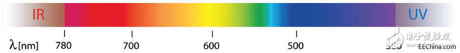
Figure 9. Spectrum
They can also optimize the optical architecture to match the critical resolution and lighting requirements of the inspection scan. The exciting thing is that developers can take advantage of advanced programmability to take 3D scanning to a new level, thereby optimizing performance in the spectral, spatial and temporal domains.
DLP product portfolio considerationsTI's advanced light control product portfolio provides DMD and supporting controller imaging capabilities beyond traditional displays. It is worth mentioning that the wavelength range supported by the DMD chip is between 363 nm and 2500 nm, the binary pattern rate is up to 32 kHz, and it can provide more precise pixel accuracy control. The following is an explanation of how DLP chipsets with advanced light control optimize structured light systems.
DMD characteristicsï¬ Resolution—At the time of writing this publication, the DMD resolution range reached 0.2 to 4.1 million pixels (MP). In environments where a larger scanning area or strong light intensity is required, larger 1-MP, 2-MP or 4-MP DMDs tend to be used. For example, automotive 3D inspection requires a large area scan on the bright factory floor during assembly and alignment processing steps. DMDs smaller than 1-MP tend to be placed in relatively portable and low-power small handheld or desktop devices.
ï¬ Power — The smallest chipset power consumption is less than 200mW, which is very suitable for portable or battery-powered systems. For example, the intraoral scanner is to make full use of the form factor of the small DMD and its advantages of low power consumption suitable for battery power supply.
ï¬ Wavelength—Users can adjust the color and lighting intensity in a system based on DLP technology according to the reflection characteristics of the object. Because DMD can be combined with various light sources, including lamps, light-emitting diodes (LED) and lasers. DMD is optimized for ultraviolet (363-420nm), visible light (400-700nm) and near infrared (700-2,500nm). For biometric 3D scanning solutions, near-infrared wavelengths are widely favored because of their non-invasive characteristics. Ultraviolet rays are sometimes the best choice to optimize the reflective properties of metals. The LED optical laser is an energy-saving monochromatic solution for white light images.
Controller characteristicsï¬ Pre-stored mode-DLP controller provides a convenient interface for reliable and high-speed DMD control. They support pre-stored structured light images without the need for an external video processor to transmit the images.

Figure 10.1D image example
Some DLP controllers can use one-dimensional (1D) encoding to pre-store more than 1,000 structured light row and column images (for example, see Figure 10). The characteristic of 1D image is that its information can be expressed by a single row or a single column of information. Professional 3D handheld scanner products usually use 1D images to reduce costs and increase scanning speed. More advanced controllers support up to 400 pre-stored 2D full-frame modes (for example, see Figure 11), which can be more adapted to X and Y according to the needs of the application or the object being scanned.
ï¬ Image accuracy and speed — DLP controller is designed to display patterns suitable for machine vision or digital exposure, and supports variable high-speed pattern display rates, up to 32,000 patterns per second, and has a camera synchronization function. These image rates are crucial for high-precision and high-speed 3D scanning systems.
From simple to complex systems, DLP technology provides customers with incredible image flexibility when designing customized structured light system hardware and algorithms.
DLP products for 3D scanningTI provides a series of DLP chipsets to adapt to different 3D scanning requirements, as shown in Table 1 below. For the latest and complete list of DLP chips, please refer to TI DLP Technology.
Table 1. DLP chipset combinations that can display useful 3D scanning specifications
DMD Micromirror Array Optimal Wavelength Controller Maximum Image Rate High-speed Pre-stored Image Display
Diagonal line (binary / 8 bits) (2D or 1D)DLP2010 854 × 480 0.20†420–700-nm DLPC3470 2, 880-Hz / 360-Hz 1D only
DLP2010NIR 854 × 480 0.20†700–2, 500-nm DLPC3470 2, 880-Hz / 360-Hz 1D only
DLP3010 1280 × 720 0.3†420–700-nm DLPC3478 2, 880-Hz / 360-Hz 1D only
DLP4500 912 × 1140 0.45†420–700-nm DLPC350 4, 225-Hz / 120-Hz 2D
DLP4500NIR 912 × 1140 0.45†700–2, 500-nm DLPC350 4, 225-Hz / 120-Hz 2D
DLP4710 1920 × 1080 0.47†420–700-nm DLPC3479 1,440-Hz / 120-Hz 1D only
DLP5500 1024 × 768 0.55†420–700-nm DLPC200 5,000-Hz / 500-Hz 2D
DLP6500 1920 × 1080 0.65†420–700-nm DLPC900 9,523-Hz / 1,031-Hz 2D
DLP6500 1920 × 1080 0.65†420–700-nm DLPC910 11, 574-Hz / 1,446-Hz —
DLP7000 1024 × 768 0.7†400–700-nm DLPC410 32,552-Hz / 4,069-Hz —
DLP7000UV 1024 × 768 0.7†400–700-nm DLPC410 32,552-Hz / 4,069-Hz —
DLP9000 2560 × 1600 0.9†400–700-nm DLPC900 9,523-Hz / 1,031-Hz 2D
DLP9000X 2560 × 1600 0.9†400–700-nm DLPC910 14,989-Hz / 1,873-Hz —
DLP9500 1920 × 1080 0.95†400–700-nm DLPC410 23, 148-Hz / 2,893-Hz —
DLP9500UV 1920 × 1080 0.95†400–700-nm DLPC410 23, 148-Hz / 2,893-Hz —
This ratchet wrench is often used to tighten up the hexagonal head bolts. It is convenient to be used, providing high speed. The specification mentioned in the following table refers to the dimension of opposite sides of hexagonal head.
Ningbo MARSHINE Power Technology Co., Ltd. is a professional engaged in the development, design and manufacture of power engineering construction equipment and tools.
MARSHINE company produces circuit construction tools, including foundation construction, tower group lap. Wiring structure. Cable construction, cable construction, mobile knife mill, insulated overhead cable and high voltage Cable Stripper, all kinds of aluminum alloy pull rod, guide rail, grounding device, high strength shackle, ratchet wrench and pointed wrench, double hook tight line device, lifting pulley, nylon wheel and aluminum wheel, punching machine ect.
MARSHINE continues to carry forward the enterprise spirit of "integrity, development, innovation" and strive for the prosperity and development of the electric power industry.
Welcome to contact MARSHINE and reach cooperation, thank you!
ratchet wrenches,Ratcheting Wrenches,Adjustable Ratchet Wrench,Ratchet Wrench Set
MARSHINE , https://www.puller-tensioner.com