S7-200 is a small-scale programmable controller, which is suitable for the automation of detection, monitoring and control in all walks of life and various occasions. The powerful features of the S7-200 series make it possible to implement complex control functions, whether in stand-alone operation or connected to a network. Therefore, the S7-200 series has a very high performance/price ratio.
The advantages of s7-2001) Extremely high reliability.
2) Very rich instruction set.
3) Easy to master.
4) Convenient operation.
5) Rich built-in integration features.
6) Real-time characteristics.
7) Strong communication capabilities.
8) Rich extension modules.
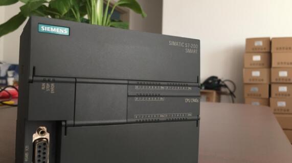
1. S7-200 has 6 kinds of CPU module, can expand 7 expansion modules at most, expand to 256 digital I\O or 45 analog I\O, have 24KB program storage space and 10KB user data storage space at most.
2. Integrate six high speed counters with 13 operating modes and two high speed pulse generators/pulse width modulators. The maximum counting frequency of the high-speed counter of the CPU 224XP is 200 kHz, and the highest frequency of the high-speed output is 100 kHz.
II: Advanced Program StructureThe program structure of the S7-200 is simple and clear. In the programming software, the main program, subroutines, and interrupt programs are stored in separate pages. Use local variables in each block. It is easy to quickly migrate programs to other projects. Subroutines use input and output parameters as software interfaces to implement structured programming. The S7-200's instructions are powerful and easy to master.
Three: Flexible and convenient memory structureThe input (I), output (Q), bit memory (M), sequence control relay (S), variable memory (V), and local variable (L) of the S7-200 can be (bit), byte, word, and Double word reading and writing.
Four: powerful, easy-to-use programming softwareThe programming software STEP 7-Micro\WIN can use many languages ​​including Chinese. There are ladder diagrams, statement tables and function block diagram programming languages, as well as SIMATIC, IEC61131-3 two programming modes.
Five: Wizard Functions to Simplify Complex Programming TasksProgramming and application such as PID control, network communication, high-speed input, high-speed output, position control, data recording, recipes, and text displays are difficult points in PLC program design. Programming them using common methods is both tedious and error-prone.
VI: Powerful Communication FunctionThe CPU module of the S7-200S has one or two standard RS-485 ports that can be used for programming or communication and can be used with other S7-200, S7-300\S7-400 PLCs, frequency converters and computers without additional hardware. Communication. The S7-200 can use communication protocols such as PPI, MPI, Modbus RTU Slave, Modbus RTU Master, and USS, as well as the Freeport communication mode.
Can s7-200 communicate directly with modbus?S7-200 cannot directly implement communication modbus. S7-200 communication modbus method steps are as follows:
Claim:To use the Modbus protocol you must first install the instruction library on STEP7 Micro/Win.
The Modbus master protocol only supports STEP7 Micro/WinV4.0 SP5 and above. .
1. Hardware settings
2 parameter matching
3. The address of the instruction store
4. Keep the register worth transferring
1. Hardware settingsThe Modbus communication in the routine is performed between the communication ports 0 of two S7-200 CPUs (preferably, each CPU has two communication ports). The master station side can also select the corresponding library file "MBUS_CTRL_P1" and "MBUS_MSG_P1" to communicate via communication port 1. Communication port 1 establishes a PG or PC connection with Micro/WIN. Communication ports 0 of the two CPUs are connected by PPI cables (pins 2,3,7,8 are connected).
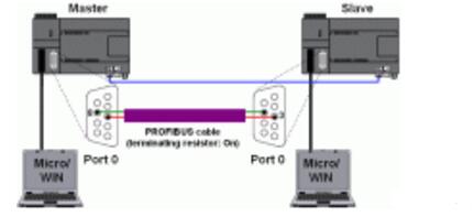
Figure 01
2 parameter matchingFor MODBUS communication, the master station needs the library "MBUS_CTRL" and "MBUS_MSG", and the slave station needs the library "MBUS_INIT" and "MBUS_SLAVE".
In Micro/WIN, you need to create a new project for the master station and slave station. The program and parameter settings are shown in Fig. 02.
It must be ensured that the "Baud" and "Parity" parameter settings of the master station and the slave station are identical, and the "Slave" address in the program block "MBUS_MSG" must be the same as the "Addr" in the program block "MBUS_INIT". (See Fig. 02).
The baud rate of the 0 communication port set in the Micro/WIN "system block" is irrelevant to the MODBUS protocol ("Mode"="1").
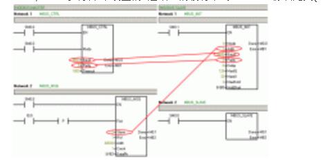
Figure 02
The following table lists the various parameters of the program block options and their significance
Main site
MBUS_CTRL
Parameter Meaning Option EN Enable Mode Protocol Selection 0=PPI, 1=MODBUSBaud Transmission Rate kbps1200,2400,4800,9600,19200,38400,57600,115200 Parity Check Option 0=No Check, 1=Odd Check, 2= Even check the longest response time of TImeout from the station msDone "Complete" flag bit Error Error code 1) Table 01
1) See STEP 7 Micro/WIN help: "Error code MBUS_MSG when MODBUS master executes MBUS_MSG".
MBUS_MSG
Parameter Meaning Option EN Enable First Read/Write Request Bit Slave Slave Address RW "Read" or "Write" 0 = Read, 1 = Write Addr Reads and writes the data address 0 of the slave. .128 = Digital output Q0.0. .Q15.7
1001. .10128 = Digital input I0.0. .Q15.7
30001. .30092=Analog input AIW0. .AIW62
40001. .49999=Retainer register 2Count Number of bits or words (0xxxx, 1xxxx)/words (3xxxx, 4xxxx) DataPtrV memory area start address pointer Done 'Finished' flag bit Error Error code 1) Table 02
1) See STEP 7 Micro/WIN help: "Error code MBUS_MSG when MODBUS master executes MBUS_MSG".
Slaves
MBUS_INIT
Parameter Meaning Option EN Enable Mode Protocol Selection 0 = PPI, 1 = MODBUSAddr Slave Address Baud Transmission Rate kbps 1200, 2400, 4800, 9600, 19200, 38400, 57600, 115200 Parity Check 0 = No check, 1 = Odd check , 2 = even parity Delay timeout msMaxIQ Number of digital input and output points that can be used 2) Number of analog input points that can be used by MaxAI 2) MaxHold Maximum number of register words held 2) HoldStart of the holding register (40001) Done completed Flag Bit Error Error Code 3) Table 03
2) The largest address depends on the type of CPU used and its maximum value.
3) See STEP 7 Micro/WIN help: "Error code for MODBUS slave protocol".
MBUS_SLAVE
Parameter Meaning Option EN Enable Done Completion Flag Error Error Code 3) Table 04
3) See STEP 7 Micro/WIN help: "Error code for MODBUS slave protocol".
3. The storage address of the libraryAfter the project is completed, the storage address of the library must be defined in Micro/WIN. After the storage area is defined, it must be ensured that it can no longer be used by other programs (master side: "DataPtr" + "Count" slave Side: "HoldStart" + "MaxHold").
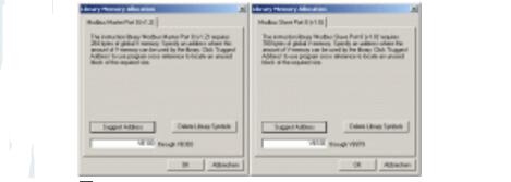
Fig. 03
4. Keep the transfer of register valuesAfter downloading the program to the appropriate CPU, you can assign a value to the V-bank of the master station in the status table, and then monitor the change of the slave.
When the master's I0.0 is enabled, the contents of VW2 are sent to the slave and written to the slave's VW2.
The transfer of holding register values ​​is shown in the figure. 04.
The pointer "DataPtr" represents the starting address where the V area is read.
The parameter "Count" indicates the number of addresses "Addr" = "4xxxx" (holding registers) are read in units of words.
The V memory area read in the master station is written in the holding register of the address "Addr" = "40002" ("RW" = "1").
The holding register works in units of words and corresponds to the address of the slave station's V area.
The pointer "HoldStart" specifies the initial address of the V memory area corresponding to the holding register start address 40001.
The V-zone target pointer for the slave can be calculated as follows:
2*(Addr-40001)+HoldStart=2*(40002-40001)+&VB0=&VB2
In addition, to ensure that the data area defined by "MaxHold" can contain the data area to be written on the master side:
MaxHold"=Addr-40001+Count=40002-40001+1=2
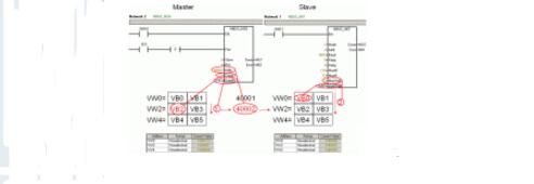
Fig.04
More information on the STEP7Micro/WINMOBDUS library can be found in the S7-200 system manual (EntryID1109582) and the STEP7 Micro/WIN help.
How to find ModbusRTU protocol and USS protocol operation library in STEP7Micro/WIN?
Explanation:
In STEP 7 Micro/WIN, the Modbus RTU protocol and USS protocol operations libraries are located in the "Libraries" folder of the operations tree. The MODBUS library requires STEP 7 Micro/WIN to be V3.2 or higher.
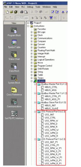
Figure 1: Add library
These libraries are additional libraries and are not part of the configuration software STEP7 Micro/WIN.
If you need to use the Modbus RTU protocol, you must purchase the "SIMATIC STEP7 Micro/WINADDON: FuncTIonLibrary V1.1 (USS+MODBUS) for STEP7 Micro/WIN32" software.
The order number for this optional additional library is 6ES7830-2BC00-0YX0.
Installation sequence:
First install "STEP7Micro/WIN32Toolbox V1.0" (including the library) and then install "STEP7Micro/WIN".
note:
This library contains the Modbus RTU protocol library and the USS protocol library that can be used in STEP 7 Micro/WINV3.2.
If you have installed STEP 7 Micro/WINV 4.0 SP5 or higher, the following functions are included in the operation library:
ModbusRTUMasterV1.2 corresponds to port 0 and port 1
ModbusRTUSlaveV1.0 corresponds to port 0
USS protocol V2.3 corresponds to port 0 and port 1
-------------------------------------------------- -------------------------------------------------- --
Siemens S7-200CN decryption method and processPLC decryption download address related to this section: http://
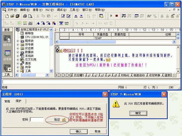
1, Siemens S7-200's PLC password is divided into three levels, we are most concerned about is the system password, because it directly affects the upload of the program, but also we have to break the key layer of the password. The second is the POU password. For Siemens 200 PLC, although you have cracked the system password and uploaded the program, each POU displays a small lock. You cannot open the program and directly affect the editing of the program. The second one is the project password, which is generated by the programmer after completing the project for security and under the "setting password" under the "file" of the programming software.
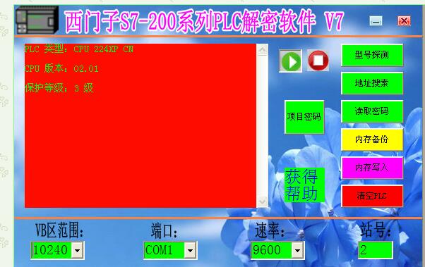
2. First, connect the PPI programming cable with PLC. If you don't have a programming cable, then you can develop one! Look at the decryption software diagram below, which is a fully licensed version that was developed in 2014 without registration. You can use it only after downloading and decompressing it.
3, solution subroutine (pou password) is the need to replace STEP7-MicroWIN's datamanagers200.dll file, so that in the "View" menu "Properties" inside the "protection" without entering a password you can open the subroutine; see the crack process .
4, on the crack patch installation and replacement methods:
If you are using programming software STEP7-MicroWINV4.0.6.35SP6 version. Copy (datamanagers200.dll) to the "C:\Program Files\Siemens\STEP7-MicroWINV4.0\bin\ folder to overwrite the original file. The subroutine requires STEP7-MicroWINV4.0.3.08SP3, Siemens at a minimum. The software version updates are SP4, SP5, and SP6, respectively, and now it has reached SP7 version, which is not suitable for low version or other versions.The respective versions need their own crack patches, which are not common to each other.
5, on the PLC version 02 (cn) system password cracking statement:
The new version of plc adds a fourth level of protection, which prohibits reading and writing, whether or not you know the password. How is the so-called new version different? First, the hardware records the version number in the bottom line of the bottom label of the PLC. Secondly, look at the type of CPU marked on the front of the PLC, such as 226CN. If there is a "CN" character, then the version number must also be version 02. The third is the communication read version number, you use STEP7-MicroWIN to connect the PLC, click the upload button, then the pop-up dialog box clearly shows the PLC's CPU model and version number. Therefore, it is the version number that distinguishes between the old and new versions, with CN being just one of them, and there are also four-level encryption without CN. It can also be said that all four-level encryption is called the new version. It is indeed difficult to crack this version, but it is not like Siemens said that it cannot be cracked and everything is flawed.
CN's decryption suite is now on sale. Now it is basically possible to determine the range of Siemens S7-200 PLCs that can be cracked by the PPI protocol: the following 02.00 versions, including some 02.00 versions (exactly only the highest level 3 encryption plc), can be easily cracked by this software, 02.00 Above version, including 02.00 version (precise positioning is - 2.0 version with 4 encryption functions) and all 200CN models, only disassemble decryption, so far no better way! About the version number, you can detect it through this software.
China leading manufacturers and suppliers of DC Support Capacitors,DC Capacitor, and we are specialize in Electrolytic capacitor,High Voltage Capacitor, etc.DCMJ DC Support Capacitors
DCMJ DC Support Capacitors,Capacitors High Voltage,Dc-link Filter Capacitor,Dc Film Capacitors
YANGZHOU POSITIONING TECH CO., LTD. , https://www.pst-thyristor.com