Application area: industrial automation
This article refers to the address: http://
Challenge: Solve the functional test of the car wiper (scraping angle and wiping frequency), durability test (scraping 1.5 million times) and watering control of the car windshield (including the adjustment of the water spray interval and water volume) .
Application: Use the LabVIEW programming software from Nationl Instruments to collect, process, and control the wiper system.
Use product: Labview8.6 software development
Platform; NI PCI-7831R data acquisition card
Introduction
The wiper is an important part of the car, which ensures that the car can drive safely in rainy days, and its performance directly affects the car's driving conditions. In order to ensure the reliability of the wiper, the wiper factory test requirements must reach 1.5 million wipe cycles. Nowadays, the control system constructed by PLC plus touch screen is popular, but its shortcoming is that the data processing function is weak, and its function is far less than LabVIEW. LabVIEW can collect, process and analyze data and express it in image form. Data storage is convenient.
Software interface design
The test software is designed according to our company's corporate standards, the interface is clear and beautiful. See picture (a).
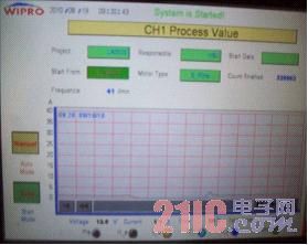
Figure 1 test interface
The operation interface is divided into a main interface, a parameter setting interface, a test interface, a waterway control interface, an angle test interface, and a data storage interface. The operation mode is divided into manual and automatic. The upper part of the test interface displays information. The parameter setting interface is in another interface, which can set the number of wiping times, cycle time, etc. The lower part of the test interface is the displayed wiping frequency, motor current curve and value. , motor temperature, running time, cycle time and the status of each solenoid valve; the waterway control interface uses the simulated pipeline way to design the waterway control map, each pipeline is drawn with a custom Boolean control, the waterway control mode is clear at a glance; The angle test interface can display 10 sets of recently measured angle values.
Wiper angle measurement
The data acquisition card collects the number of pulses sent by the rotary encoder, and then uses LabVIEW to convert the angle value. For example, if the encoder sends 3600 pulses in one turn, the angle value when receiving n pulses is: Theta=πn/1800(rad)=n/10(°)
The sampling time is set according to the actual situation, which is generally specified as follows:
f(t) ≥ scraping frequency / 120 (s)
LabVIEW based on data acquisition card
The wiper angle can be calculated by the maximum number of pulses received during the sample time.
Wiper frequency measurement
The data acquisition card collects the +5V voltage signal of the proximity switch, and the counter +1 records the time at the moment with LabVIEW, and then continues to collect the next letter.
No., then subtract the time of the last acquisition from the time of the last acquisition, which is twice the time interval t ms. The wiping frequency is calculated as follows: f=60000/t (times/min)
The sampling time is generally set to: t ≤ f(t) ≤ 2t
The wiper frequency changes in real time during actual measurements due to load changes in the wiper system.
Waterway control
The waterway control is mainly realized by the on/off of the solenoid valve by LabVIEW. See Figure (2) When wet scraping is required, the solenoid valve is opened and water is sprayed onto the windshield through the pipeline; when dry scraping is required, the solenoid valve is closed and the return valve is opened; when the liquid level sensor has a signal When the pump is turned back on until the level sensor generates a signal again, the control of the feed pump is controlled by the relay. When the output of the data acquisition card outputs a signal, the relay is turned on, thus turning on the pump. Each solenoid valve is indirectly controlled by a relay, and the on/off of the output terminal of the data acquisition card directly controls the on and off of the relay.
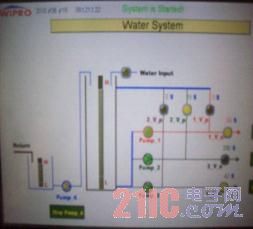
Figure 2 Waterway Control Interface
In the automatic mode, the automatic operation is performed according to the set dry and wet scraping time. The total number of scraping is the N end of the For cycle. When the set time is reached, a signal is output to the relay to control the on and off of the corresponding solenoid valve.
Wiper motor monitoring
The wiper motor monitoring includes two parameters: motor current and case temperature. The motor current is measured by the current transmitter to deliver the current to the data acquisition card, so that the current is displayed on the screen as a curve through LabVIEW, so that the current is monitored in real time. If the current exceeds the set value, the system stops running.
The motor temperature is measured by a thermocouple. The electrical signal generated by the thermocouple enters LabVIEW through the data acquisition card. After conversion, the actual temperature is generated. When the motor temperature exceeds the upper limit of the temperature setting, the system stops running.
data processing
Use LabVIEW's powerful data processing capabilities to process data and generate report formats. LabVIEW automatically saves data to a specified path at regular intervals and generates reports in word format. This can be done with the LabVIEW Report Generation Toolkit. The information contained in the report includes time, wiper angle, wiper frequency, motor temperature, wiper status, and number of wipes.
in conclusion
The test system can meet the requirements of the function and durability of the wiper in the major automobile OEMs at home and abroad. Open structure, easy to maintain; high sensitivity, voltage accuracy 0.1v, current accuracy 0.1A, angle 0.1°; due to the use of industrial computer, good environmental performance, and cost-effective; test system interface designed with virtual instrument technology More beautiful, more convenient to operate.
Constant voltage design,24V/12V DC output,with the range of 20w to 350w. Specifically and perfectly work for LED strips. As a class II power unit, the LPV drivers are housedwith the UL 94V-0 rated flame retardant plastic enclosure. The IP67 design allows every model to fit the use at dry, damp and wet locations. There are two types of dimming driver ,such as triac driver,0-10V driver.All drivers have the features of short circuit protection,overload protection,over voltage protection.Three years warranty,UL,CE,TUV certificated.
Waterproof Led Driver,Waterproof Electronic Led Driver,Led Driver Waterproof,Waterproof Led Driver Ip67
Guangdong Kamtat Lighting Technology Joint Stock Co., Ltd. , http://www.ip68ledstrip.com