When there is a problem with the pressure of the car tires, it will not only reduce the service life of the tires and increase the fuel consumption, but may even lead to dangerous situations such as punctures. Statistics show that 70% of traffic accidents on highways in China are caused by tire pressure problems. The proportion of causes of tire accidents is: tire pressure is too high, accounting for 20%, tire pressure is less than 57%, and others are 23%. Punctures occur when the speed is above 160 km, and the death rate is as close as 100%. Therefore, puncture has become one of the major killers of current car traffic accidents. The automobile tire pressure monitoring sensor can accurately measure the current tire pressure and temperature value in real time. When the tire is in an abnormal dangerous situation, the sensor will send a signal to the vehicle's instrument display and alarm through the radio signal to achieve the real-time reminder of the driver's effect and eliminate the accident. In the bud.
This article refers to the address: http://
System specification
A tire pressure monitoring sensor is installed inside each wheel, which can accurately measure the pressure and temperature inside the tire. The sensor sends the pressure value and temperature value of the tire to the automobile meter according to a certain law through the 433.92MHz RF wireless form. The driver passes the driver. The dashboard display gets the pressure and temperature values ​​for each tire. When the pressure value or temperature value of a certain tire changes beyond the alarm value, the instrument panel can accurately display the position of the alarm tire and issue a graphic, sound, and text alarm. At the same time, the tire pressure monitoring sensor receives the 125 kHz low frequency antenna data information installed at the position of each tire fender to realize two-way communication of the system. Since this product is a safety part for automotive products, it should have high reliability in various environments. Various environments are: cloudy weather, rain and other weather conditions; national roads, high-speed, rural roads, mountain roads and other road conditions; snow roads, ice surfaces, extremely cold regions (-40 ° C) in winter; hot in summer , wet areas (surface temperature +50 ° C, 90% humidity); different speeds (0 ~ 200km / h). This requires strict selection of individual devices when designing automotive tire pressure monitoring sensors.
Circuit design
Since the automobile tire pressure monitoring sensor is installed inside the tire and is not in contact with the outside world, this requires maintenance and repair that cannot be performed too frequently. Generally, it requires a working life of 10 years or 100,000 kilometers, and its operating temperature range is: -40~ +125 ° C, which requires the selected device to be automotive grade and low power components.
The block diagram of the automobile tire pressure monitoring sensor system is shown in Figure 1. 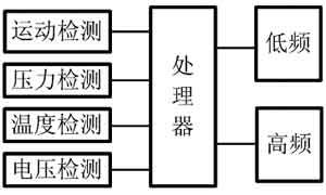
Figure 1 system composition block diagram
The system is divided into an acquisition part, a processing part, and a driving part. The acquisition part is pressure detection, temperature detection, voltage detection and motion detection. Temperature sensing is used to measure the internal temperature of the tire and also for temperature compensation during pressure measurement. Pressure detection is used to measure the absolute pressure inside the tire; voltage detection is used to measure the voltage of the power supply battery; motion detection is used to monitor the driving state of the vehicle; and the driving part is composed of a low frequency drive and a high frequency drive. The low frequency driver is responsible for 125 kHz low frequency data reception, the high frequency driver is responsible for 433.92 MHz high frequency data transmission; the processing part is completed by the MCU, and is responsible for coordinating the acquisition part and the driving part according to a certain algorithm strategy.
The system device selects SP37 of Infineon (Infineon), and all the functional processing modules of Figure 1 are integrated in the chip. SP37 chip specific performance is: working voltage 1.9 ~ 3.6V; working temperature -40 ~ +125 ° C; pressure measurement range 0 ~ 450kPa; Z-axis motion acceleration -115 ~ +115g; temperature measurement -40 ~ +125 ° C; battery voltage AD detection; integrated ISM band 315/434MHz RF transmission; RF output power (50Ω load) 5~8dBm; hardware Manchester/bidirectional coded RF transmission; RF ASK/FSK modulation; FSK frequency offset up to 50kHz; integrated high sensitivity 125kHz low frequency receiver; hardware Manchester low frequency decoding; 16bit hardware CRC generator; controller compatible with 8051 instructions; 6KB Flash program storage space; 16KB ROM library function storage space; 256Byte RAM data storage space; Power Down, Idle, Run and Int four operating modes; interval timer, low frequency receive or external pin interrupt three wake mode; 8bit hardware random number generator; watchdog timer; 3 I / O ports.
The circuit schematic based on SP37 is shown in Figure 2. 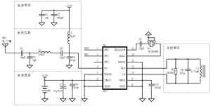
Figure 2 SP37 circuit schematic
1 high frequency circuit design
The system high-frequency working frequency selects the European tire pressure monitoring system to specify the band 433.92MHz, SP37 internal integrated VCO and PLL, the high-frequency frequency is 24 times the external crystal frequency, so the choice of automotive grade 18.08MHz passive crystal, load capacitance 8pF, crystal connection as shown in picture 2. Since the FSK modulates different carrier frequencies according to the digital signal 1 or 0, the noise and attenuation are good, and the ASK turns on or off the carrier according to the digital signal 1 or 0, but its noise resistance is poor and susceptible to interference, so the system Use FSK modulation method. SP37 selects the internal capacitor mode modulation FSK. By setting the XTAL1 and XTAL0 register parameters, the frequency offset is adjusted to 50kHz and the center frequency is 433.92MHz.
SP37 internal integrated RF PA transmitting unit, its output impedance is 15.02+j53.219Ω, impedance matching is performed by π-type matching circuit, and the matching value is calculated by ADS software simulation. The specific value is shown in the RF matching unit in Figure 2. Figure 3 shows the results of a Smith matching chart using ADS software. 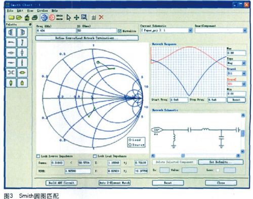
There are three levels of RF power output, namely 1PA, 2PA and 3PA, and the power is from small to large. The system sets the RFTX.PAOP to 11b and uses 3PA to amplify the power, so that the spectrum tester can test the RF output power to 10.52dBm.
2 low frequency circuit design
The LF low frequency communication is responsible for the SP37 receiving low frequency information. The low frequency antenna consists of parallel resistors, capacitors and inductors. In order to achieve optimal low frequency receiving sensitivity, the resonant frequency of the inductor and capacitor is designed to be a low frequency carrier frequency of 125 k Hz. The low-frequency inductor uses PREMO TP1103-0477, the inductance is 4.77mH, and the capacitance is: 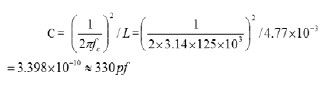
The shunt resistor R is mainly used to reduce the quality factor Q of the LCD resonant circuit to a low frequency sufficient bandwidth (7.8 k Hz). The quality factor of the resonant circuit Q = fc / BW = 1 2 5 k H z / (2 × 3.9k H z) = 15, which requires that the quality factor Q of the LF resonant circuit cannot be greater than 15. The resistance R = Q × XL = 15 × 2π × fc × L = 49.5 k Ω can be calculated. The specific circuit is shown in Figure 2 low frequency receiving unit.
Since the S P37 low frequency reception baud rate hardware is set to 3.9 kbps Manchester code. Figure 4 shows the relationship between low frequency carrier data transmission and Manchester code. 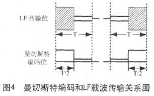
Since the hardware has been solidified to a 3.9 kbps Manchester code baud rate, each transmit bit time is calculated to be 3.9 kbps x 2 = 7.8 kbps by calculating LF.
The low frequency receiving information frame format is shown in Figure 5. 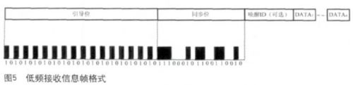
RF data transmission needs to interact with information in this format. The pilot bit is first transmitted 32 bits, followed by an 18-bit sync code, followed by the wake-up ID and user DATA data in Manchester format.
3 battery selection
The battery selects the high temperature series battery (C R2450H R) from Japan's Maxell Battery Company, the power supply voltage is +3.6V, and the battery capacity is 480m A h. It has the characteristics of long life, high energy density, low self-discharge electrode and light weight (8.8g). ), the temperature limit is wide (-55 ~ +125 ° C).
Antenna design
The performance of the antenna will directly affect the quality of the data transmission, which is an important factor in the increase of the transmission power of the vehicle tire monitoring sensor. The antenna of the automobile tire monitoring sensor is close to the valve. Therefore, when designing the antenna, the shielding of the tire wire must be considered, the reflection effect of the rim metal, and the influence of the antenna changing direction and angle when the wheel rotates at a high speed, etc., so the antenna design must be considered. The following factors: the linear polarization is easily affected by the attitude of the antenna. The rotating wheel has a relatively high requirement for the working polarization of the antenna. The connection between the antenna and the RF module needs to solve the problem of impedance matching, which is also the focus of the antenna design; The pressure sensor is installed in the tire and is affected by the performance of the body and antenna movement. The miniaturized design, the antenna installed inside the tire must consider the miniaturized design, the working frequency of 433.92 MHz, the wavelength is 691.37mm, the conventional antenna The size must not meet the requirements.
Based on the above considerations, we consider the use of the valve as the antenna of the transmitting module. This kind of antenna has the advantages of easy processing, low cost, easy integration design and easy matching. The valve installation method is shown in Figure 6. 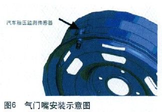
The valve antenna is a commonly used antenna form for automobile tire monitoring sensors at home and abroad, and it belongs to the category of small electric antennas. The design of the small antenna is focused on the design of the structure size and the setting of the matching circuit. Because the radiation resistance of the small antenna is generally small (a few ohms), the radiation efficiency of the small antenna is generally low, and the radiation impedance often exists. In the imaginary part, this energy storage factor will lead to further reduction in radiation efficiency. The imaginary part can be solved by the matching circuit, but the real part resistance needs to match the impedance of the RF output pin of the transmitting chip, which is also the design focus of the transmitting small antenna. The antenna loading method adopted in this scheme is loaded by the internal matching brass piece, which is similar to the inverted F antenna loading mode. After the bench test and the road test, it shows that our design idea and matching method are effective. 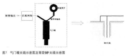
software design
The software functions of the system: periodic measurement of tire pressure and temperature value; variable periodic emission of tire pressure and temperature value; low frequency radio frequency data receiving and processing; air pressure high alarm function; low air pressure alarm function; high temperature alarm function; fast air leak Alarm function; battery voltage low alarm function; sensor no signal alarm function. The system requires a lifetime of 10 years. To achieve such a long service life, the system is in a sleep state under normal conditions, and the quiescent current is only 0.6 μA. The system sleep state can be awakened by a low frequency LF interrupt or an interval timer interrupt. The system software framework flow chart is shown in Figure 8. 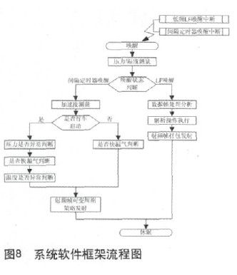
S P37 internal ROM comes with the underlying library function (Library Function), the user can directly call the library function. The use of library functions greatly simplifies programmer software development and software reliability. Library functions include sensor measurement functions, low frequency interface control functions, high frequency interface control functions, and other processing functions. The sensor measurement function includes: measuring pressure or motion acceleration M ea s_P ressure function, measuring temperature M ea s_T emperatu re function, measuring battery voltage Meas_Supply_Voltage function, measuring acceleration Meas_Acceleration function; low frequency interface control function including: low frequency baud rate calibration LFBaudrateCalibration Function; high-frequency interface control functions include: enable crystal operation S tart X tal O sc function, stop crystal work ST op X tal O sc function, VCO work VC O_T uning function, transmit RF frame
S en d_R F_T elegram function; other processing functions include: P owerdown function, CRC8 check CRC8_Calc function, CRC16 check CR C16_C heck function, read device identification code R ea d_I D function, 16-bit data multiplication SM ul I nt I The nt function, interval timer calibrates the IntervalTimerCalibration function, and obtains the hardware version number FW_Revision_Nb function.
Since the tire pressure sensor installed inside each tire may have the possibility of transmitting high frequency data at the same time, radio frequency interference will occur between the data, which causes the BCM controller RF receiver to receive the correct data, which is a data conflict. Data collisions are randomly generated and cannot be avoided, but the probability of recurring data collisions after collisions is reduced, avoiding continuous data collisions. At present, the system adds a random delay between each transmitted high frequency data frame, and the random delay time is a prime multiple of the data frame time length, that is, 3 times, 5 times, 7 times, 11 times and 13 times. Thus, if there is a data collision in the previous module, the data collision will only occur again when the random delay time of the module transmitting the conflict is the same, the probability is 4%.
Structural design
The tire pressure sensor is mounted inside the car tire and consists of a valve, a housing and a dust cap. The driving speed of the car can reach up to 250k m/h, and the internal environment of the tire is complex and extremely bad. It is in the environment of high pressure, high humidity, alternating temperature, oil pollution, bumpy vibration for a long time. The change in temperature tends to embrittle the shell and reduce the mechanical strength. In high-humidity conditions, the shell expands, the strength decreases, and chemical reactions such as corrosion occur. Tires travel on a variety of roads, and the amplitude of the bumps varies from one frequency to the other. These conditions can cause loose parts. This requires the system structure design to consider the following points: the total weight of the system is light (less than 40g), the speed of rotation acceleration is high, the structural breaking strength is high, the sealing is high (I P6 protection level), the structure and the valve material are selected to withstand High and low temperature and corrosion resistant materials, anti-loose design at the joint between the valve and the rim.
in conclusion
Tire pressure sensor Whether the bench test or road test in various situations, the system maintains high reliability, the system low-frequency transmission accuracy and high-frequency transmission and reception accuracy rate reaches 98%. When the tire is in an abnormal dangerous situation, the car dashboard displays relevant alarms. The information reminds the driver in real time that the accident caused by the tire pressure problem is eliminated in the bud, which enhances the safety of the car. The successful application of this system will bring higher use value and social value to the vehicle driving safety system.
We offer service for Network Cabling Products in following series: 19" Floorstanding Cabinets in 18U to 45U, Wall mount cabinets and frames, regular patch panel in 6port to 48port,hot sale on 24port cat.5e UTP patch panel,24 port angle patch panels, over 30 kinds of various horizontal and vertical wire management panel,Cat.5e and Cat.6 Patch Cords, toolesskeystone jacks accordingly.

Network cabling products Quality Control Instruction:
To offer a perfect product, we every worker pay attention to each detail of our network cabling products. With our company aim, first in our purchase department, our purchaser compares strictly in raw material suppliers to control cost but keep quality, our mold workshop makes inspection before plastic parts turned to production line .Before installation, our production line first will inspect on plastic parts and other components. During production procedure ,there is tester in steps according different products needs. After installation, the Quality Control members will make a full inspection on characters, appearance according our specification.
Network Cabling Products
19" Floor Cabinet, Cat.5e Patch Panel, Cable Management Bars, Angled Patch Panel, Cat.6a Sheilded Keystone Jack, Cat.6a UTP Keystone Jack, Network Cabling Products, Cat5 Network Cable, Patch Panel.
NINGBO YULIANG TELECOM MUNICATIONS EQUIPMENT CO.,LTD. , https://www.yltelecom.com