With the advancement of computer technology, the Finite Difference Time Domain (FiniteDifference TImeDomain) is a numerical calculation technique for solving electromagnetic problems, which was proposed by KSYee in 1966. His basic idea is to use the difference of the field component of the Maxwell's equation in the time domain and replace the differential with the difference to perform the iteration of each field component. However, with the increase of the frequency, the computational grid will increase significantly, the performance of the PC. It will be difficult to meet the needs, and it is not practical to rely solely on the improvement of computer performance. For example, in the analysis of the waveguide diaphragm filter, in order to correctly simulate the geometry of all the diaphragms, the grid size of the FDTD grid is chosen to be very small, resulting in a very large number of grids describing the entire waveguide filter. Since there is a uniform waveguide transmission line between every two diaphragms, it is obviously unnecessary to use the same grid as the diaphragm. People have used a non-uniform FDTD grid to solve this problem. When the grid size is relatively large, not only is the convergence difficult to control, but it still cannot save computation time. The DiakopTIcs idea is applied to the full-wave analysis of the microwave circuit. By dividing the circuit into several independent parts, different meshes are used according to the specific structure of each part, and the full-wave time-domain analysis is performed on each part independently, due to the The grid is uniform, so it is easy to guarantee the convergence of the algorithm.
Second, the concept of DiakopTIcsThe concept of DiakopTIcs comes from the theory of networks. It is defined as: decomposing a network into several sub-networks, solving the impact response of each sub-network separately, and finally obtaining the total response of the network by the impulse response of the sub-networks through certain connection conditions. Connection conditions can be divided into serial connection and parallel connection according to different forms. The serial connection is one-way connection from one end of the network to the other end in a certain order. See Figure 1. The advantage is simple, but the biggest problem is that when the impact response of one of the sub-networks changes, the network will be followed. Have an impact. Parallel connections overcome this shortcoming. The parallel connection can be performed between any two adjacent sub-networks, and several parallel connections can be performed independently at the same time. Parallel time domain Diakoptics assumes that the sub-network is an M+N port network, where M ports are connected to the previous-level sub-network. N ports are connected to the latter subnet. The discrete Green's function of the subnetwork is g(i,j,n'), ie the excitation of j(j=1, M+N) at port t=0, at i(i=1, M+N) port t=n 'The impact response of the moment.
When studying the microwave circuit problem, if the microwave circuit can be equivalent to a linear network, it can be assumed that the Green's function describing the characteristics of the microwave circuit can correspond to the impulse response function in the circuit theory. From the perspective of electromagnetic field theory, the time domain Green's function g(r, t; r0, t0) is the field of the unit shock signal applied at the point source t0 at the r0 point at the observation point r and t, and satisfies the equation.
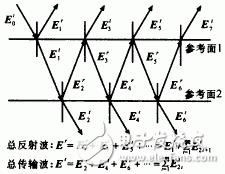
When two microwave sub-circuits are connected, there is a complex coupling relationship on the connection reference surface. This coupling relationship can be visualized by electromagnetic waves reflected and transmitted in a medium with two discontinuous interfaces, as shown in Fig. 1. . So how do you apply the Diakoptics algorithm to the analysis of microwave circuit characteristics? Before introducing this point, this article first briefly introduces the mathematical description of the Diakoptics algorithm.

Figure 1 The reflection and transmission phenomena in the medium can be used to graphically describe the coupling relationship between two microwave sub-circuits.
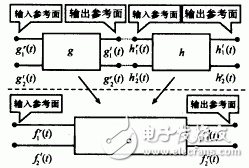
Third, the mathematical description of the Diakoptics algorithmA mathematical description of the Diakoptics algorithm is given in a string, parallel connection of two two-port networks. Figure 2 assumes that the impulse response functions of the reflected and transmitted waves of the two sub-circuits are: gr1(t), gr2(t), gt1(t), gt2(t) and hr1(t), hr2(t), ht1( t), ht2(t), the superscript "r" denotes a reflected wave, "t" denotes a transmitted wave, the subscript 1 denotes an excitation from the input reference facing circuit, and the subscript 2 denotes an excitation from the output reference facing circuit. Let f be the impulse response function of the circuit after the two sub-circuits are connected. Using the serial algorithm, the impulse response seen from the f network input reference plane is:
Fr1(t)=gr1(t)+gt2(t)*hr1(t)*gt1(t)+gt2(t)*hr1(t)
*gr2(t)*hr1(t)*gt1(t)+...+gt2(t)*(hr1(t)
*gr2(t))n*hr1(t)*gt1(t)+...; (2)
Using the parallel algorithm, the impulse response functions fr1(t), ft2(t) seen from the input port of the f-circuit and the impulse response function fr2(t), ft1(t) seen from the output port of the f-circuit are:
Fr1(t)=gr1(t)+gt2(t)*hr1(t)*gt1(t)+gt2(t)*hr1(t)
*gr2(t)*hr1(t)*gt1(t)+...+gt2(t)*(hr1(t)
*gr2(t))n*hr1(t)*gt1(t)+...
Ft2(t)=gt2(t)*hr2(t)+gt2(t)*hr1(t)*gr2(t)*ht2(t)+...
+gr2(t)*(hr1(t)*gr2(t))n*hr2(t)+... (3)
Fr2(t)=hr2(t)+ht1(t)*gr2(t)*ht2(t)+ht1(t)*gr2(t)
*hr1(t)*gt2(t)*ht2(t)+...+ht1(t)*(gr2(t)
*hr1(t))n*gr2(t)*ht2(t)+...
Ft1(t)=ht1(t)*gt1(t)+ht1(t)*gr2(t)*hr1(t)*gt1(t)+...
+ht1(t)*(gr2(t)*hr1(t))n*gr1(t)+...
Among them, * represents the time domain convolution, and the meaning of the superscript is unchanged.

Figure 2 illustrates the connection of two subcircuits of the Diakoptics algorithm.
·Basic precautions
Do not put expensive oil into low-quality cartridges to avoid wastage. Most pre-filled oil cartridges have the so-called 510 thread. The oil cartridge screws onto a rechargeable battery. Some of these batteries have buttons and some heat up automatically when you pump the oil. Some batteries have multiple temperature settings and some heat up to a preset temperature; these features need to be known in advance.
·Cleaning notes
Use a suitable cleaning tool to clean them, such as activated charcoal or dried tea leaves in a used pipe to absorb the oil. It is important not to use alcohol or other boiling water to clean the pipe, and to wait until it has cooled down completely before cleaning. Otherwise, the hot stem will come into contact with the watery liquid and cause the mouthpiece tenon to loosen, thus shortening the life of the 510 cartridges.
This is what you should be aware of when using 510 cartridges. At the same time, when using 510 cartridges, there are still some vaping tips, for example, when using them, be careful not to suck too hard, will not produce smoke. When you inhale too hard, the smoke is sucked directly into your mouth and not atomized by the atomizer, so gently inhaling is more powerful and gives you a better vaping experience.
510 Cartridge Oem,Leakproof 510 Cartridge,510 Battery And Cartridges Oem,510 Cartridge
Shenzhen MASON VAP Technology Co., Ltd. , https://www.cbdvapefactory.com