0 Preface
Since the Industrial Revolution, with the development of electrical, humans have entered a new stage of civilization. Robots have been widely used in industry, agriculture, service industry, military, machinery, transportation, aerospace and other fields. The continuous improvement of the level of intelligent robots has greatly improved labor efficiency and reduced labor intensity. Robots fight side by side with humans and play an important role in conquering nature and transforming nature.
The smart car is a comprehensive system that integrates multiple disciplines such as theoretical mechanics, mechanical structure, digital circuits, analog circuits, sensors, single-chip computers, control theory and algorithms, and its contents cover machinery, electronics, automatic control principles, computers, and sensor technology. And many other disciplines and fields.
The smart car based on ATmagel6L designed in this paper is required to start from the starting line, and then automatically adjust the direction and speed by itself, so that it automatically runs along a black guide line.
1 Hardware design of smart car
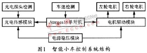
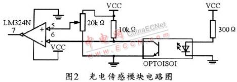
The structure of this intelligent car control system is shown in Figure 1. Among them, Atmegal6L MCU is the control module of the smart car, it is a high-performance, low-power 8-bit AVR microprocessor, using advanced RISC structure, with 16K bytes of system-programmable Flash and 512 bytes of EEPROM. When working at 16 MHz, its performance is up to 16 MIPS, and has 32 programmable universal I / 0 ports and a JTAG interface for boundary scan, which can basically meet the design requirements. The circuit voltage regulator module inputs 12 V. After the voltage regulator circuit, two voltages of 9 V and 5 V can be obtained, of which 9 V is used for the working voltage of the motor drive module, and 5 V is used for the work of the single chip microcomputer. Figure 2 shows the circuit diagram of the RPR220 photoelectric sensor module. The photoelectric sensor is composed of 10 RPR220 photoelectric pairs. RPR220 is an integrated reflective photodetector whose transmitter is a gallium arsenide infrared light-emitting diode and the receiver is a high-sensitivity silicon planar phototransistor. The L298N's INPUT and OUTPUT ports are used to provide a stable voltage to rotate the motor.
1.1 Photoelectric sensor module
Figure 2 shows the circuit diagram of the photoelectric sensor module in this system. The hunt path is generally a 3 cm black line engraved on the white plane. The car follows the black line. When a white line is detected, that is, the light emitted by the diode is reflected back by the white line, the phototransistor guides the transistor. Through, the input of port 6 of the comparator is low, and after the comparator, the output of port 7 is high. When a black line is detected, the light is absorbed, the light intensity is weakened, the phototransistor transistor is not conductive, the input of the comparator terminal 6 is high level, and the output of terminal 7 is low level. After feeding the high-low level (l and 0) to the single-chip microcomputer through the PC port, it can be used to adjust the steering of the vehicle head after being processed by the single-chip microcomputer, so that the black line is just in the middle of 10 photoelectric probes, so that the trolley can move forward smoothly. Connect a 0.1μF capacitor on the 7th end and then ground, so that the square wave that enters the microcontroller after filtering is perfect. Connect this photocell to the code wheel, and continuously scan the code cell number through the photocell. In this way, when the code wheel rotates and the speed is low, the signal at the 6th terminal can become a square wave with a frequency corresponding to the speed. However, when the speed of the code wheel is very fast, the signal at the 6th end will become a sinusoidal signal with a one-to-one frequency and speed correspondence. The amplifier LM324 can be used as a comparator. After comparing the sinusoidal signal at the 6th terminal with the reference voltage, a square wave corresponding to the frequency and the speed will be generated at the 7th terminal. The formula calculates various parameters of the DC motor to accurately control the steering and displacement of the car.
1.2 Motor drive module
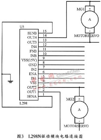
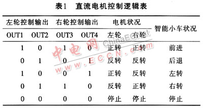
Figure 3 shows the circuit connection diagram of the L298N drive module. L298N is a high-voltage and high-current full-bridge driver chip as a motor driver chip. It has a high frequency, can control two DC motors, and has a control enable terminal. The operating voltage can be input 9 V through pins 4 and 9 , 5 V voltage. The ENA and ENB pins are two enable ports, while INT and OUT are motor drive pins. By changing the logic level of the OUT terminal, the positive, negative, and stop states of the motor can be controlled. Table 1 lists the DC motor control logic . The six pins of 5, 6, 7, 10, 11 and 12 of the L298N can be directly connected to the PD port of the single-chip microcomputer, and the PWM speed regulation of the DC motor can be realized by programming the single-chip microcomputer.
l. 3 SCM control module
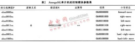
Atmell6L microcontroller from Atmel can be used to control the trolley. The microcontroller has 32 powerful programmable I / O interfaces and 4 PWM channels. It has eight 10-bit ADCs and can control the trolley in real time. The eight ports PC0 ~ PC7 of the single-chip microcomputer can be connected with the eight photoelectric probes of the photoelectric sensor module. Suppose the logical actual value detected by the probe is P, the assumed value N, and the motion states of the wheels are forward-move, right-move, leftmove, hard-right-move, hard-left-move. The comparison of N (0b0011-1100) can be obtained from the control module parameter table of the Atmegal6L microcontroller listed in Table 2, where x is an irrelevant item. During design, PD2 ~ PD3 of Atmegal6L can be connected to two photoelectric counter tubes with code discs respectively for precise measurement of steering and displacement of wheels; PD5 and PD4 can be connected to the ENA and ENB of the motor drive module respectively . PD1, PD0, PD6, and PD7 are connected to IN1, IN2, IN3, and IN4 of the motor drive module. The IN1 and IN2 ports are generally used for PWM input, so as to use the PWM speed regulation method, that is, a series of fixed frequency outputs Wave, and drive the motor through the power amplifier, and then change the duty cycle of the output square wave through the single-chip programming, so that the average voltage applied to the motor can be changed, thereby changing the speed of the motor.
2 Software design scheme of smart car
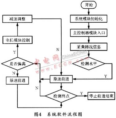
The flow chart of system software based on AVR microcontroller and C language programming is shown in Figure 4.
3 Conclusion
This article focuses on the principles of photoelectric sensors, single-chip microcomputer control and voltage regulators and the mutual communication and coordination between these modules. This system uses cheap infrared pair of tubes and uses ATmagel6L single-chip microcomputer with powerful functions as the main controller. At the same time, the L298N driver chip is used to write debugging software through the C language program, thereby completing the design of an intelligent car capable of intelligent tracking, automatic obstacle avoidance, modular structure, and strong anti-interference ability. The system can make the car run smoothly on any given black line through the debugging of the car, and the tracking effect is very good, the operation is very stable, and the speed is also very fast, and there will be no large speed at the corner And there is a centrifugal phenomenon.
The smart car has been widely used in the fields of military, civil, scientific research, and aerospace exploration. Its development is closely related to automatic control, single-chip development, optimization of control algorithms, and microcomputer storage processing speed. It is worthy of further research and exploration.
Since the Industrial Revolution, with the development of electrical, humans have entered a new stage of civilization. Robots have been widely used in industry, agriculture, service industry, military, machinery, transportation, aerospace and other fields. The continuous improvement of the level of intelligent robots has greatly improved labor efficiency and reduced labor intensity. Robots fight side by side with humans and play an important role in conquering nature and transforming nature.
The smart car is a comprehensive system that integrates multiple disciplines such as theoretical mechanics, mechanical structure, digital circuits, analog circuits, sensors, single-chip computers, control theory and algorithms, and its contents cover machinery, electronics, automatic control principles, computers, and sensor technology. And many other disciplines and fields.
The smart car based on ATmagel6L designed in this paper is required to start from the starting line, and then automatically adjust the direction and speed by itself, so that it automatically runs along a black guide line.
1 Hardware design of smart car
The structure of this intelligent car control system is shown in Figure 1. Among them, Atmegal6L MCU is the control module of the smart car, it is a high-performance, low-power 8-bit AVR microprocessor, using advanced RISC structure, with 16K bytes of system-programmable Flash and 512 bytes of EEPROM. When working at 16 MHz, its performance is up to 16 MIPS, and has 32 programmable universal I / 0 ports and a JTAG interface for boundary scan, which can basically meet the design requirements. The circuit voltage regulator module inputs 12 V. After the voltage regulator circuit, two voltages of 9 V and 5 V can be obtained, of which 9 V is used for the working voltage of the motor drive module, and 5 V is used for the work of the single chip microcomputer. Figure 2 shows the circuit diagram of the RPR220 photoelectric sensor module. The photoelectric sensor is composed of 10 RPR220 photoelectric pairs. RPR220 is an integrated reflective photodetector whose transmitter is a gallium arsenide infrared light-emitting diode and the receiver is a high-sensitivity silicon planar phototransistor. The L298N's INPUT and OUTPUT ports are used to provide a stable voltage to rotate the motor.
1.1 Photoelectric sensor module
Figure 2 shows the circuit diagram of the photoelectric sensor module in this system. The hunt path is generally a 3 cm black line engraved on the white plane. The car follows the black line. When a white line is detected, that is, the light emitted by the diode is reflected back by the white line, the phototransistor guides the transistor. Through, the input of port 6 of the comparator is low, and after the comparator, the output of port 7 is high. When a black line is detected, the light is absorbed, the light intensity is weakened, the phototransistor transistor is not conductive, the input of the comparator terminal 6 is high level, and the output of terminal 7 is low level. After feeding the high-low level (l and 0) to the single-chip microcomputer through the PC port, it can be used to adjust the steering of the vehicle head after being processed by the single-chip microcomputer, so that the black line is just in the middle of 10 photoelectric probes, so that the trolley can move forward smoothly. Connect a 0.1μF capacitor on the 7th end and then ground, so that the square wave that enters the microcontroller after filtering is perfect. Connect this photocell to the code wheel, and continuously scan the code cell number through the photocell. In this way, when the code wheel rotates and the speed is low, the signal at the 6th terminal can become a square wave with a frequency corresponding to the speed. However, when the speed of the code wheel is very fast, the signal at the 6th end will become a sinusoidal signal with a one-to-one frequency and speed correspondence. The amplifier LM324 can be used as a comparator. After comparing the sinusoidal signal at the 6th terminal with the reference voltage, a square wave corresponding to the frequency and the speed will be generated at the 7th terminal. The formula calculates various parameters of the DC motor to accurately control the steering and displacement of the car.
1.2 Motor drive module
Figure 3 shows the circuit connection diagram of the L298N drive module. L298N is a high-voltage and high-current full-bridge driver chip as a motor driver chip. It has a high frequency, can control two DC motors, and has a control enable terminal. The operating voltage can be input 9 V through pins 4 and 9 , 5 V voltage. The ENA and ENB pins are two enable ports, while INT and OUT are motor drive pins. By changing the logic level of the OUT terminal, the positive, negative, and stop states of the motor can be controlled. Table 1 lists the DC motor control logic . The six pins of 5, 6, 7, 10, 11 and 12 of the L298N can be directly connected to the PD port of the single-chip microcomputer, and the PWM speed regulation of the DC motor can be realized by programming the single-chip microcomputer.
l. 3 SCM control module
Atmell6L microcontroller from Atmel can be used to control the trolley. The microcontroller has 32 powerful programmable I / O interfaces and 4 PWM channels. It has eight 10-bit ADCs and can control the trolley in real time. The eight ports PC0 ~ PC7 of the single-chip microcomputer can be connected with the eight photoelectric probes of the photoelectric sensor module. Suppose the logical actual value detected by the probe is P, the assumed value N, and the motion states of the wheels are forward-move, right-move, leftmove, hard-right-move, hard-left-move. The comparison of N (0b0011-1100) can be obtained from the control module parameter table of the Atmegal6L microcontroller listed in Table 2, where x is an irrelevant item. During design, PD2 ~ PD3 of Atmegal6L can be connected to two photoelectric counter tubes with code discs respectively for precise measurement of steering and displacement of wheels; PD5 and PD4 can be connected to the ENA and ENB of the motor drive module respectively . PD1, PD0, PD6, and PD7 are connected to IN1, IN2, IN3, and IN4 of the motor drive module. The IN1 and IN2 ports are generally used for PWM input, so as to use the PWM speed regulation method, that is, a series of fixed frequency outputs Wave, and drive the motor through the power amplifier, and then change the duty cycle of the output square wave through the single-chip programming, so that the average voltage applied to the motor can be changed, thereby changing the speed of the motor.
2 Software design scheme of smart car
The flow chart of system software based on AVR microcontroller and C language programming is shown in Figure 4.
3 Conclusion
This article focuses on the principles of photoelectric sensors, single-chip microcomputer control and voltage regulators and the mutual communication and coordination between these modules. This system uses cheap infrared pair of tubes and uses ATmagel6L single-chip microcomputer with powerful functions as the main controller. At the same time, the L298N driver chip is used to write debugging software through the C language program, thereby completing the design of an intelligent car capable of intelligent tracking, automatic obstacle avoidance, modular structure, and strong anti-interference ability. The system can make the car run smoothly on any given black line through the debugging of the car, and the tracking effect is very good, the operation is very stable, and the speed is also very fast, and there will be no large speed at the corner And there is a centrifugal phenomenon.
The smart car has been widely used in the fields of military, civil, scientific research, and aerospace exploration. Its development is closely related to automatic control, single-chip development, optimization of control algorithms, and microcomputer storage processing speed. It is worthy of further research and exploration.
We have experience and skill to support customers to tooling for their required waterproof connectors, like IP68 series,micro fit connectors. Etop wire assemblies for various industries have been highly recognized by all the customers and widely used for automobiles, electrical and mechanical, medical industry and electrical equipemnts, etc. Products like, wire harness for car audio, power seat, rear-view mirror, POS ATM, Diesel valve Cover gasket fit, elevator, game machine, medical equipment, computer, etc.
JST Connector,Molex Connector, Multi-Contact Connector, Micro Fit Connectors
ETOP WIREHARNESS LIMITED , https://www.etopwireharness.com