introduction
This article refers to the address: http://
Using image sensors to sense the road traffic environment and obstacles in front of the road, to achieve safe distance measurement, timely warning of vehicles in danger of collision is conducive to reducing traffic accidents and improving road traffic safety. Because the theoretical calculation of the safe distance is first of all to ensure the safety, it is often different from the safe distance recognized by the driver during the driving process, which leads to the driver's distrust of the early warning system, which is not conducive to the promotion of the system. use. At the same time, as the processing platform of the safety assisted driving system, the volume, cost and redundancy of the PC are bottlenecks that are difficult to overcome in the in-vehicle system.
Based on the image measurement of the distance between the vehicle and the preceding vehicle, this paper establishes a vehicle longitudinal collision warning model to solve the contradiction between the theoretically calculated safety distance and the driver's approved custom distance; consider the real-time processing of the embedded system. With the characteristics of small size and compactness, the embedded method is used to complete the design of the vehicle longitudinal collision warning system.
1 Measurement of front distance
The image sensor is fixed on the top of the front of the vehicle and the height of the camera is h from the ground. The space coordinate system is established as follows:
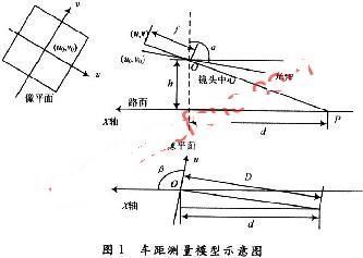

World coordinate system XYZ and camera coordinate system xyz. The dynamic world coordinate system moves with the vehicle, with the vertical projection point of the camera lens center on the ground as the origin, the vertical line of the ground is the Z-axis forward direction, the longitudinal axis of the vehicle body is the X-axis, and the forward direction is the opposite direction of the car forward. The camera coordinate system has the optical axis as the z-axis, the lens center as the coordinate origin, and the camera coordinate xy plane parallel to the image plane; the u-axis and the v-axis of the image plane coordinate system representing the position of each point inside the image are parallel to the x-axis and the y-axis. The origin is at the center of the image, which is the intersection of the camera's optical axis and the image. All coordinate systems satisfy the right-hand rule.
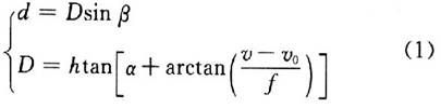
Measurement of the vehicle or obstacle ahead by the image sensor includes ranging using single frame images and ranging using multi-frame images. Considering the installation position parameters of the camera in the study, the angle between the camera z coordinate axis and the X axis is called the scan angle β, and the angle between the camera optical axis (z axis) and the vertical direction (Z axis) is called the tilt angle α. As shown in Figure 1. In the figure, the camera external parameters α, β, h and the internal parameter camera focal length f are obtained by strict camera calibration. The vehicle image recognition and Kalmam filtering principle are used to realize the recognition of the vehicle, and the computer image coordinates of the P point at the bottom of the vehicle are known. The point (u0, v0) is the plane coordinate origin (O, 0); the point (u, v) can be calculated from the P point computer image coordinates (m, n) according to the internal parameter model formula
obtain. Where kx, ky is the magnification factor of the digital image in the x-axis and y-axis directions; Om, On is the computer image coordinate of the origin of the image plane. According to the perspective projection and the triangular geometric relationship, the distance between the two cars is calculated by the formula (1):
In order to verify the calculation accuracy of formula (1), after completing the camera calibration, the pedestrian crossing line of the road is taken, and the horizontal distance between each pedestrian crossing line and the camera lens center is measured, and compared with the distance calculated according to the ranging model, the result is shown in Table 1. Shown. In the table, the error between the measured distance and the calculated distance includes the measurement error and the model error. It can be seen from the table that the error is within the permissible range and can meet the next processing requirements.
2 Determination of the driving state of the preceding vehicle
The driving state of the preceding vehicle affects the early warning moment of the vehicle longitudinal collision warning model. The judgment of the preceding vehicle state is based on the relative distance and relative speed between the vehicle and the preceding vehicle. According to the image sequence frame, the current time and the next-time workshop distance between the vehicle and the preceding vehicle are measured, and the instantaneous speed of the current time and the next time is obtained by the speed sensor of the vehicle, and then:
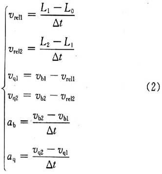
In the formula: L2, L1, L0 are the distances of the vehicle and the preceding vehicle measured at different times (unit: m); vb1, vb2, vq1, vq2 are the speeds of the car and the preceding car at different times (unit: m/ s); vrel1, vrel2 are the relative speeds of the vehicle and the preceding vehicle at different times; ab, aq are the deceleration of the vehicle and the preceding vehicle at that moment (unit: m/s2); Δt is the interval time (unit :s).
(1)|vq1, vq2|<εv, the preceding vehicle is at rest, εv is the measurement tolerance, and the value is determined experimentally.
(2)|vq1,vq2|>εv, and |vq1-vq2|<εv, and vq1
(3)|vq1,vq2|>εv, and |vq2-vq1|>εv, and vq2 ![]()
3 Longitudinal collision warning algorithm based on vehicle state and safety factor
3.1 Establishment of longitudinal collision warning model
The vehicle longitudinal collision warning system must maintain the driver's trust in the system while ensuring the safety of the road and ensuring the road capacity. If the early warning safety distance of the early warning system is often greater than the driver's own judgment on the safe distance, Frequent alarms from the system may cause the driver to ignore the system's alarm signal or abandon the use of the system. The early warning algorithm designed in this paper uses the state of the preceding vehicle to determine the safety factor, improves the early warning timing control of the system, improves the safety performance of the system early warning, and increases the trustworthiness of the system.
The minimum safe distance warning algorithm is established as follows:
Where: Ld is the safe distance of the warning system when the alarm starts; Ls is the minimum safe distance calculated according to the theory of automobile braking and the different states of the vehicle and the preceding vehicle; γ is the weight of the safety factor based on the state of the preceding vehicle. The formula for calculating the minimum safe distance Ls is as follows:
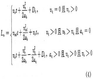
Where: t is the brake operation reaction time (unit: s); vs, vq is the initial speed of the car and the front car before braking (unit: m / s); vrel is the relative initial speed of the two cars (unit: m/s-); D0 is the safety distance when the two cars are stopped or the speed of the two cars is equal, generally 2~5m.
The rules for the value of the safety factor γ are as follows:

The front car is at a standstill, or the front car is driving at a constant speed and the speed of the car is faster than the preceding car, that is, aq=0. The safe distance calculated by the maximum deceleration of the car is reasonable. In actual traffic, the driver takes less of the maximum deceleration operation considering the ride comfort, and measures have been taken before the minimum safe distance is reached. The main function of the early warning model is to remind the driver of the operational status when negligence or distraction. Therefore, the safety factor weight γ=1.
When the front car suddenly decelerates, there are three situations:
(1) The deceleration speed of the two vehicles is equal, which satisfies the general conditions of road traffic. The safety distance calculated by this case is the base number, and the safety factor weight γ is determined by measuring the deceleration of the preceding vehicle.
(2) The deceleration of the vehicle is less than the deceleration of the preceding vehicle. The braking performance of the vehicle is worse than that of the preceding vehicle, but the probability of occurrence is not much.
(3) The deceleration of the vehicle is greater than the deceleration of the preceding vehicle. The braking strength of the vehicle is higher than the braking strength of the preceding vehicle, or the braking strength of the vehicle changes with the change of the preceding vehicle, and is always higher than the preceding vehicle. Common situation. At this time, the calculated safety distance is too small, which is not suitable as a warning basis.
In summary, when aq=0, γ=1 as described above; when aq<5.0 m/s2, the vehicle deceleration ability is higher than the preceding vehicle deceleration, taking γ=0.8; when 5.06.9 m In /s2, considering the unfavorable condition, the deceleration of the vehicle is less than the deceleration of the preceding vehicle, taking γ=1.2.
3.2 Test verification
On the structured road, the Wulingguang 6400C3 extended version mini-car was selected as the experimental vehicle. The above-mentioned warning time based on the preceding vehicle state and safety factor was used to verify the warning time of the vehicle following distance. The results show that the system can reliably give an early warning and the inter-vehicle distance at the time of the warning is acceptable to the driver.
Figure 2 is a screenshot of the alarm time when the vehicle is driving at a constant speed and the vehicle is accelerating. At this time, the workshop distance is 24.895 m, and the relative speed of the two vehicles is 5.513 m/S;

Figure 3 is a screenshot of the alarm time when the vehicle is driving at a constant speed of 90 km/h. At this time, the workshop distance is 45.847m, and the relative speed of the two vehicles is 8.571m/s.

4 system design
The real-time performance of the vehicle longitudinal collision system requires the processor to have faster running speed and stronger real-time scheduling capability. The research uses the design and production of DaVinci (Davinci) by Texas Instruments (TI), based on DSP and The ARM9 dual-core TMS320DM6446ZWT System-on-Chip (SoC) evaluation board is used as the hardware platform of the system, and the Linux system is selected as the embedded operating system.

The system first receives the image transmitted by the image sensor, converts the color image into a gray image to be processed, and uses image processing such as median filtering, Sobel operator edge detection, adaptive threshold segmentation, etc. to eliminate the noise smooth image. Edge detection and image segmentation yield a binarized image.
Based on the binarized image and the grayscale image, the front vehicle contour is identified, the front vehicle contour size and the position of the bottom edge in the plane image are determined, and the following distance calculation and safety distance are realized according to the vehicle longitudinal collision warning model. Early warning. The software flow chart is shown in Figure 4.
5 Conclusion
The vehicle longitudinal collision warning algorithm based on the front vehicle motion state and safety factor weight is proposed to ensure the driving safety while ensuring the traffic capacity of the road. The calculation of the alarm distance is consistent with the driver's approved safety distance of the car, which improves the system. Trustworthiness; the application of embedded systems effectively reduces the size of the system, which is conducive to the application and promotion of the system.
Specifications
1.Steel Processed Reel
2.In accordance with GB4004-83, JB/T7600.3-94 and DlN46395 standards
- choice of flange with or without ribs
- extra stiffeners in the drum
- painting
- hot galvanizing
- stainless steel version
- dynamic balancing
|
Serial Number |
Specification Model
|
Lateral Plate Diameter D1
|
Major Diameter D2
|
Axle Hole Diameter D4
|
Carrying Hole Diameter D5
|
Center Distance E of Axle Hole and Carrying Hole
|
External Width L1
|
Internal Width L2
|
|
1
|
315
|
315
|
120
|
33.5
|
16
|
86
|
238
|
200
|
|
2
|
400
|
400
|
160/200
|
56
|
16
|
71-112
|
300
|
250
|
|
3
|
440
|
440
|
220
|
80
|
16-28
|
180
|
316
|
292
|
|
4
|
450
|
450
|
180/224
|
56
|
16-28
|
71-112
|
335
|
280
|
|
5
|
500
|
500
|
250
|
56
|
16-28
|
142
|
335
|
315
|
|
6
|
560
|
560
|
224/280
|
56
|
16-28
|
71-112
|
425
|
355
|
|
7
|
600
|
600
|
250/300
|
56/60
|
16-28
|
71-112
|
340/3
85 |
300/3
50 |
|
8
|
630
|
630
|
335
|
80
|
16-32
|
140
|
495
|
450
|
|
9
|
710
|
710
|
355/400
|
80
|
28-40
|
71-112
|
530
|
450
|
|
10
|
760
|
760
|
355
|
32.5/54
|
21-35
|
64-115
95-126.5 |
345
315 |
295
280 |
|
11
|
762
|
762
|
355/400
|
60
|
25-40
|
135
|
360
|
280
|
|
12
|
787
|
787
|
450
|
127
|
25.4
|
120
|
560
|
485
|
|
13
|
800
|
800
|
450
|
200
|
28-40
|
135
|
600
|
500
|
|
14
|
900
|
900
|
380
|
80
|
28-40
|
400
|
764
|
720
|
|
15
|
1000
|
1000
|
500
|
200
|
28-40
|
320
|
780
|
660
|

Punching Wire Spool, Pressed Steel Spool, Single Wall Reel, Pressed Bobbin
NINGBO BEILUN TIAOYUE MACHINE CO., LTD. , https://www.spool-manufacturer.com