The 2SA2151 and 2SC6100 are high power pair tubes for new audio amplifiers. Based on the technical parameters provided by the manufacturer and the experience of some of the self-made amplifiers, the author has built a power amplifier that is very suitable for household use. The circuit is now available for your reference.
This article refers to the address: http://
Circuit selection scheme
The author's listening room area is 21 square meters, and the speaker is a self-made imitation Ls3/5a two-way monitor. Due to the opportunity to contact a variety of audio equipment, after comparison, it was decided to make a multi-timbral comparable amplifier. The voltage amplification part is selected from the form of an operational amplifier, a transistor discrete part, and an electron tube type, and is switched by a switch for comparison. The final stage current amplifier stage adopts 0dB pure class A non-negative feedback form, and the circuit is shown in Figure 1. 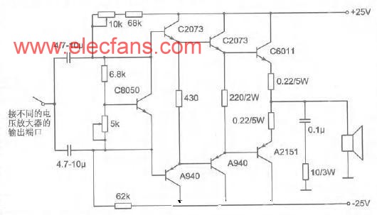
The choice of this circuit form is mainly based on the following aspects:
1. The use of pure Class A working form can basically eliminate crossover distortion and switching distortion. These two kinds of distortions cannot be overcome by ordinary Class B power amplifiers.
2. The use of no large loop negative feedback can eliminate transient intermodulation distortion and interface intermodulation distortion caused by loop negative feedback. Both of these distortions are dynamic indicators, and the two methods of quantitative measurement are both cumbersome, so the whole product does not have the technical indicators of these two kinds of distortion. Transient intermodulation distortion has a great influence on the quality of the playback sound. Generally, this indicator is not paid much attention to. The interface intermodulation distortion is a new dynamic distortion generated by the back-EMF generated by the voice coil when the speaker is working through the loop negative feedback to the amplifier input stage. When the intermodulation distortion is severe, the reproduced sound will be opaque. All amplifiers with large loop negative feedback have this problem, but the degree is different.
The 3.0dB pure Class A non-negative feedback power amplifier has no voltage gain, which is a test for the performance of the voltage amplification stage. Since there is no negative feedback loop, other indicators such as harmonic distortion and damping factors are guaranteed by the circuit itself and component quality.
Component installation and commissioning
The general current amplification stages are composed of two stages. The power tube in the first stage is used to amplify the current, and the first stage is a high-power tube for large current output. In order to adapt to the output current of different voltage amplification stages, the circuit of Figure 1 adopts the Darlington structure in the current amplification stage so that a small current can meet the output rated power.
Figure 1 circuit pure class A output power is 25W (8Ω load), quiescent current 1.25A, so the static tube consumption of each power tube is 31.25W, the total static power consumption of 4 power tubes is 125w.
This circuit can be assembled by printed circuit board or directly on the heat sink in the form of lap welding. The area of ​​the radiator should meet the requirements when assembling. Generally, a radiator similar to the nominal 200W finished machine can be used. When assembled with a printed circuit board, the constant voltage offset adjustment tube 8050 should be placed close to the heat sink for temperature compensation. The two medium power tubes of each arm should be back-to-back to ensure thermal equalization. For example, lap welding requires all transistors. On the heat sink, the power supply is directly connected to the C pole of the high power tube. The adjustable resistor should use multiple precision adjustable resistors to ensure the accuracy and safety of the adjustment.
The input capacitor has a great influence on the tone, and the brand can be selected according to its own preferences. All transistors should be paired. After assembly, the power can be debugged. First adjust the 10K adjustable resistor so that the DC voltage at the output is below 10mV. If the DC voltage cannot be adjusted below 10mV, it means that the matching of the transistor is not good. The re-adjustment should be replaced. After the adjustment, the quiescent current is adjusted. Adjust the 5K adjustable resistor so that the DC voltage across the high-power tube emitter resistance (0.22Ω/5W) is 275mV. At this time, the quiescent current is 1.25A, let the amplifier stand for 1 hour in this state and then measure the mid-point DC. The voltage and quiescent current values ​​are re-adjusted if they do not match. After the adjustment, the amplifier is completed, and the different voltage amplification stages can be selected to work.
Voltage amplification stage selection and assembly
Figure 2 shows the transistor voltage amplification stage. This circuit uses the preamplifier circuit of the famous "Marantz" PM power amplifier. When the final stage power amplifier is to achieve a rated output of 25W, the voltage amplification stage should provide an undistorted voltage of 15V or more. The original circuit is used as a preamplifier, and the voltage amplification factor is only 8.5 times, which cannot meet the needs. This circuit will The voltage amplification factor was changed to 22 times to meet the needs of the final stage. Adjust the 470Ω adjustable resistor after the picture is installed so that the D669 and B649 have a quiescent current of 20 mA, which makes it work in the Class A state. 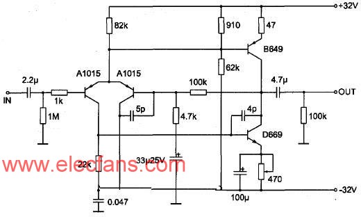
Figure 3 shows the voltage amplification stage composed of dual op amps. This circuit is mainly used to appreciate the op amp sound quality and sound quality of different grades. Since the maximum output voltage of the op amp is only 13V, the circuit is used to boost the maximum power at the final stage. Only 20W, the op amp position is assembled with a gold-plated socket to facilitate the replacement of different op amps for audition. 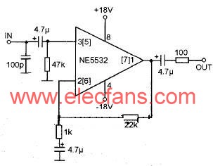
Figure 4 shows the voltage amplification stage of the tube. The circuit refers to the world famous machine "Matisse" circuit, and some changes have been made in the supply voltage and amplification to meet the needs of the final stage. The sound of this circuit is quite sweet, and it is a good match with the pure class A final level. The circuit is easy to assemble and does not need to be commissioned. 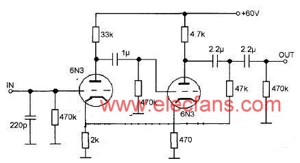
The above three voltage amplification stages should be selected with high-quality components when assembling, especially the coupling capacitors of all levels should choose the brand capacitance of the enthusiast class.
The working voltage of the last stage of the machine is comprehensively considered according to the working condition of the high power tube at 1.25A. Do not easily increase the working voltage of the last stage power tube in order to increase the output power. If the impedance of the speaker is 4Ω, the pure class A power It will be reduced to 12.5W, and the power of Class A and Class B will increase to about 60W. Since the final stage power amplifier tube does not enter the loop negative feedback network, the distortion will increase significantly when the working point enters the Class B state, so the final stage power should be readjusted. The quiescent current and working voltage of the tube shall have a 25W pure Class A power output quiescent current adjusted to 1.77A and a working voltage of ±17V at 4Ω load; at this time, the static power consumption of a single power tube is about 30W. The power can fully meet the needs in the home playback state, and the 10-inch three-way floor-standing speaker is more than enough. This is the difference between the pure class A and the class B power amplifier, and interested readers can try.
Spare parts for enignes, generators, genset controller
. Diesel engine parts: Cummins, Perkins, MTU, Mitsubishi, Volvo, Doosan, Yuchai, Wiechai, Cat
. Generator parts: Stamford, Leroy Somer, Marathon, Mecc Alte, Faraday, Engga
. Genset controller parts:Deepsea, ComAp, Deif, SmartGen
. Transformer
. Light Tower
. Sunlight Tower
. Breakers
. Radiators
. Sensors and Meters
. Lube Oil and Coolant.
. Panels
Spare Parts,Genset Controller,Engine Spare Parts,Alternator Spare Parts
Guangdong Superwatt Power Equipment Co., Ltd , https://www.swtgenset.com