 Three-phase transformers are used in various electrical equipment and AC power applications. For this reason, it is necessary to understand the three-phase winding connection method and the connection group. At present, China adopts the standards recommended by the International Electrotechnical Commission (IEC), that is, the phase difference of the electromotive force of the high and low voltage lines to determine the number of the three-phase transformer connection group.
 When the three-phase transformer high and low voltage windings are connected in different ways, the original and secondary edge potentials have different phase differences. The phase difference between the original phase and the secondary phase of the same phase is always an integral multiple of 30 degrees. Therefore, the clock representation is used in the world to identify the phase relationship between high and low voltage windings. The so-called clock representation method is to regard the primary edge potential as the long needle of the clock and always point to 0 (or 12); the secondary edge potential is regarded as the short needle of the clock, and the point to which it points is used as the label of the link group. The specific approach is to first mark each outgoing terminal of the transformer with the letter symbol. Take the A phase as an example. The first end of the high voltage winding is marked as A, the end of the high voltage winding is marked as X, the end of the low voltage winding is marked as a, and the end of the low voltage winding is marked as x. Each winding potential is defined as going from the leading end to the trailing end, that is, the potential of the high voltage winding points from A to X, and the potential of the low voltage winding points from a to x. The head and tail of the phasor is opposite to the head and tail of the actual winding. The X, Y, and Z terminals are connected to a common point, which is actually a common starting point for the phasor of the potential phasor. The arrow of the potential phasor points to the common point. For each group analyzed, draw a phasor diagram. If the potential phasor is changed to the voltage phasor, the head and tail of the voltage phasor are consistent with the head and tail of the actual winding. The X, Y, Z terminals of the winding are connected to a common point, which is actually the end of the voltage phasor. From the starting point, the arrow of the voltage phasor is outward, so that the voltage phasor can be rotated by the common point X, Y, Z, and each time the group judgment is made, only the corresponding voltage phasor can be rotated. Draw a phasor map again.
1 The phase relationship of the connection voltage of the three-phase transformer windings identifies the connection groups of the three-phase transformer high-voltage and low-voltage windings. The three-phase high-voltage winding head and tail ends are marked as A, B, C and X, Y, Z, respectively; The three-phase low-voltage winding heads and tail ends are labeled a, b, c and x, y, z. The three-phase winding phase voltages are specified from the tail end to the head end, and the high voltage winding phase voltages from X to A are U AX. The three-phase abbreviations are UA, UB, UC; the phase voltage of the low-voltage winding points from x to a to U ax, and the three phases are abbreviated to U a, U b, U c.
If the high and low voltage winding heads A and a are marked with the same polarity, the high and low voltage winding phase voltages UA and U a have the same phase and the phasor direction is the same; if the high and low voltage winding head ends A and a are marked as At the opposite polarity end, the phase voltages UA and Ua of the high and low voltage windings are in opposite phase and the phasors are in opposite directions.
The phase voltage of each phase of the three-phase transformer is the voltage of the phase winding. The line voltage is the voltage at the output terminal. The line voltage U AB is the voltage phasor difference between UA and UB.
1.1 Star-connected windings are arranged in sequence from left to right in phase sequence A, B, and C. The same-named end symbols are marked on the three-phase winding heads A, B, and C, and the three-phase winding ends X, Y, and Z are connected. together. In the wiring diagram marked the direction of the phase voltage of each winding, and then according to the phase voltage direction draw three-phase voltage, line voltage U AB phasor diagram phase voltage: UA = U <0 degrees; UB = U <-120 degrees; UC=U<-240 degrees.
Line voltage: U AB = U AU B; U BC = U BU C; U CA = U CU A.
The three-phase winding ends are connected together. X, Y, Z are equal potential zeros. The phase sequence is clockwise. The line voltage leads the phase voltage. The phasor A arrow is the A-end of the actual winding. Because the end symbol of the same name is marked at the head end A, B, C of the three-phase winding, the phasor diagram UA of the phase A is upward.
1.2 The left delta-connected windings are arranged in sequence from left to right in phase sequence A, B, and C. The same-named end symbols are marked on the three-phase winding ends A, B, and C, respectively. The three-phase winding ends X, Y, Z are connected with the head ends B, C, A respectively, that is, XB, YC, ZA are connected together. The phase voltage of each winding is marked on the wiring diagram, and the U A phase diagram of the three-phase voltage and the line voltage is drawn according to the direction of the phase voltage. The ZA join is the end of A and the end of C.
The left triangle connection is the second kind of triangle wiring in the existing textbooks. It can be seen that the voltage phasor is much simpler and more intuitive than the electric potential phasor, and the image is easy to remember.
The relationship between phase voltage and line voltage is U AB=UA; U BC=UB; U CA=UC.
The three-phase winding A head and C-tail are connected together, the phase sequence is clockwise, the line voltage and the phase voltage are in the same direction, and the phasor A arrow is the actual winding A head end. Because the end symbol of the same name is marked at the head end A, B, C of the three-phase winding, the phasor diagram UA of the phase A is upward.
1.3 The right delta-connected windings are arranged in sequence from left to right in phase sequence A, B, C. The same-named end symbols are marked on the three-phase winding ends A, B, and C, respectively. The three-phase winding ends X, Y, Z are connected with the head ends C, A, B, respectively, that is, XC, YA, ZB are connected together. The phase voltage of each winding is marked on the wiring diagram, and the U A phase diagram of the three-phase voltage and the line voltage is drawn according to the direction of the phase voltage. The YA join is the end of A and the end of B.
The right triangle connection is the first kind of triangle wiring in the existing teaching materials. The same voltage phasor is simpler and more intuitive than the phasor of the electric potential, and it is easy to remember.
The relationship between phase voltage and line voltage: U AB=-UB; U BC=-UC; U CA=-UA.
The three-phase winding A head and B tail are connected together, the phase sequence is clockwise, the line voltage and the phase voltage are in the same direction, and the phasor A arrow is the actual winding A head end. Because the end symbol of the same name is marked at the head end A, B, C of the three-phase winding, the phasor diagram UA of the phase A is upward.
Note: In the delta connection group, the phasor analysis method of the head-to-tail connection is consistent with the actual wiring form of the three-phase windings. The head-to-tail connection of the phasor diagram is the head-tail connection of the actual three-phase winding.
2 The connection group of the three-phase transformer determines the winding wiring diagram and the same name of the known three-phase transformer. The method for determining the transformer connection group is to draw the voltage phases of the high voltage (primary) winding and the low voltage (secondary) winding respectively. The quantity diagram, the phase relationship of the high voltage winding U AB and the low voltage winding U ab determines the label of the transformer connection group.
The specific steps are:
(1) Draw the connection diagram by connecting the head and tail symbols of known windings into the specified connection method.
(2) Mark the phase voltage and line voltage direction on the wiring diagram.
(3) Draw the phase voltage and line voltage phasor diagrams of the high and low voltage (primary and secondary) windings so that the end X,x of the windings is a common starting point.
(4) Determine the phase relationship between U ab and U AB according to the phase relationship (phase or reverse) of the phase voltage U a, U b, U c of the low voltage winding and the phase voltage UA of the high voltage winding. The label for the transformer connection group.
2.1 Y, y connection to the high voltage winding tail end X as a common point, draw the transformer primary phase voltage UA and line voltage U AB phasor diagram; the low voltage winding tail end x as a common point, draw the transformer secondary phase voltage U a and the line voltage U ab phasor diagram; draw the transformer secondary phase voltage U b, U c phasor diagram. The primary and secondary sides X and x are common starting points. The primary and secondary phase voltages UA and U a are in the same direction. The line voltage U ab and U AB are in the same direction. The transformer group is Y and y12. If the phase voltage U a and In the opposite direction of UA, the line voltage U ab and U AB are opposite. The transformer group should be Y, y6. Select U b, U c phasor diagram and UA in the same direction or opposite direction, can get other different Y, y connection group do not.
2.2 Y,d The left delta connection uses the end X of the high voltage winding as a common point. Draw the phasor diagram of the primary phase voltage UA and the line voltage U AB. Use the end x of the low voltage winding as the common point to draw the secondary phase voltage. The phasor diagram of U a and the line voltage U ab; the phase voltages U a, U b, U c of the secondary side are drawn with the A head and C tail connection. With the original and secondary sides X and x as common starting points, the primary and secondary phase voltages UA and U a have the same direction, and the line voltage U ab and UA have the same direction, then the transformer group should be Y, d1. If the phase voltage U a and In the opposite direction of UA, the line voltage U ab and UA are opposite, the transformer group should be Y, d7. Select U b, U c phasor diagram and UA in the same direction or opposite direction, you can get other different Y, d connection group do not.
2.3 Y,d Connect the right triangle to the common point of the high voltage winding end X, draw the phasor diagram of the primary phase voltage UA and the line voltage U AB; use the end x of the low voltage winding as the common point to draw the secondary phase voltage U a and phasor diagram of line voltage U ab; draw the secondary phase voltages U a, U b, U c phasor diagrams with A end B end connection. The primary and secondary sides X and x are common starting points. The primary and secondary phase voltages UA and U a are in the same direction. The line voltages U ab and U b are in the opposite direction. The transformer group should be Y and d11. If the phase voltage UA is equal to U a reverse direction, the line voltage U ab and U b opposite direction, the transformer group should be Y, d5. Select U b, U c phasor diagram and UA in the same direction or opposite direction, you can get other different Y, d connection Group.
In the even array, if the end symbol of the same name is marked at the tail end x, y, z of the secondary winding, the direction of the secondary voltage phasor diagram should be opposite to that of the primary phasor diagram UA. In a D, d delta connection, only the phase relationship of the right delta-connected transformer is determined by the polarity of the same name.
In the odd array, the end symbol of the same name is marked at the head end a, b, c of the secondary winding. In the D, y, Y, d connection, there is a left triangle and a right triangle. The phase relationship of the transformer is left Right triangle connection method to determine.
3 Conclusions Based on the analysis of the three-phase transformer winding star and delta connection methods, the method for determining the connection groups of three-phase transformers is studied, and the specific method steps are given. According to the three-phase transformer winding wiring diagram and the same name, determine the transformer connection group method is: draw the high voltage (primary) winding and low voltage (secondary) winding voltage phase diagram, by the high voltage winding U AB and low voltage The phase relationship of the winding Uab determines the label of the transformer connection group.
In the actual application process, the disk made of the phasor diagram of the high-voltage winding is called the original disk; the disk made of the phasor diagram of the low-voltage winding is called the sub-disk. The two plates are concentric and can rotate relative to each other. When the three-phase transformer connection group determination is made, the original disk is fixed, and only the auxiliary disk needs to be turned. The number of the auxiliary disk voltage Uab is the number of the transformer. The above analysis process does not need to draw a phasor map, which is simple and intuitive and very convenient.
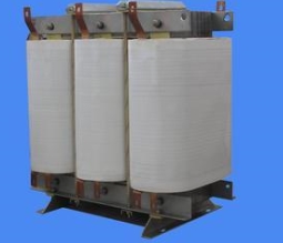
The core of SBH15 transformer produced by FGI is made of amorphous alloy material into a three-phase five-column structure, featuring low temperature rise and low loss. The transformer no-load loss is 30% of the S13 series Oil Filled Transformers. The core of the transformer, the low-voltage coil and the high-voltage coil are very tightly combined and Amorphous Core Transformers have strong short-circuit capability.
Amorphous Core Transformers
Amorphous Core Transformer,Amorphous Core Distribution Transformers,3 Phase Transformer,3 Phase Power Transformer,Amorphous Core Transformer Manufacturers In India,Amorphous Core Transformer Manufacturers
FGI SCIENCE AND TECHNOLOGY CO., LTD , https://www.fgi-tech.com