The peak current mode controlled non-continuous buck-boost converter is a good choice for LED drivers, although the output voltage may be higher or lower than the input voltage. However, when using this buck-boost converter to design a driver, a change in LED voltage will change the LED current, and an open LED will cause an excessive voltage at the output, which will damage the converter. This article discusses the converter design for LEDs in detail and presents a number of ways to overcome its inherent shortcomings.
Light-emitting diodes (LEDs) have been used for many years, and as the latest technology advances, they are becoming strong competitors in the lighting market. The new high-brightness LEDs have a long life (about 100,000 hours) and high efficiency (about 30 lumens per watt). Over the past three decades, the light output brightness of LEDs has doubled every 18 to 24 months, and this growth will continue. This trend is called Haitz's law, which is equivalent to the Moore's Law of LEDs.
Electrically, LEDs are similar to diodes in that they are also unidirectionally conductive (although their reverse blocking capability is not very good, high reverse voltage is easily damaged (LED) and has low dynamics similar to conventional diodes. Impedance VI characteristics. In addition, LEDs generally have a rated current when they are safely turned on (high-brightness LEDs are typically rated at 350mA or 700mA). When rated current is used, the LED forward voltage drop may be quite different, usually 350mA white light. The voltage drop of the LED is between 3 and 4V.
Driving the LED requires a controlled DC current. In order to make the LED have a longer service life, the ripple in the LED current must be low, because the high ripple current will cause the LED to generate large resistive power consumption and reduce the LED life. LED drive circuits require higher efficiency because the overall efficiency depends not only on the LED itself but also on the drive circuit. Switching converters operating in current-controlled mode are ideal drive solutions for high power and high efficiency requirements in LED applications.
Driving multiple LEDs also requires careful consideration. Figure 1 is a series-parallel connection circuit of LEDs. 1(a) is a parallel connection circuit of LEDs. Figure 1 (h) is a series connection circuit of LEDs. Since the dynamic impedance and forward voltage drop of each LED are not the same, if there is no external current sharing circuit (such as current mirroring), it is impossible to ensure the same current flowing through the LED; in addition, the LED string will be caused by the failure of one LED. Disconnected, causing all of the LED current to be distributed between the remaining LED strings, which will cause the current on the LED string to increase, potentially damaging the LED. Therefore, for the above two reasons, the parallel LED circuit as shown in Fig. 1(a) is generally not used in design.
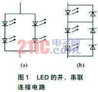
Therefore, it is better to connect the LEDs in series. The disadvantage of this method is that if one LED fails, the entire LED string will stop working. A simple way to keep the remaining LED strings working is to connect a Zener diode (which has a voltage greater than the highest voltage of the LED) in parallel with each (or each) LED, as shown in Figure 1(b). Thus, after any LED fails, its current will flow to the corresponding Zener diode, and the rest of the LED string will still work normally.
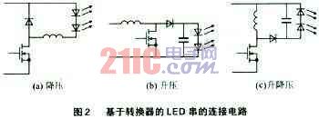
The basic single-stage switching converters can be divided into three categories: buck converters, boost converters, and buck-boost converters. When the voltage of the LED string is lower than the input voltage, Figure 2(a) is the ideal choice for the buck converter; when the input voltage is always lower than the string output voltage, the boost converter is more suitable. Figure 2(b) When the output voltage may be higher or lower than the input voltage (caused by the output or input change), it is appropriate to use the buck-boost converter as shown in Figure 2(c). The disadvantage of boost converters is that any transient in the input voltage (which can cause the input voltage to rise above the output voltage) can cause a large current flow on the LED (due to the low dynamic impedance of the load), which can damage the LED. The buck-boost converter can also replace the boost converter because transients in the input voltage do not affect the LED current.
The working principle of the buck-boost converter
For LED drivers in low voltage applications, buck-boost converters are a good choice. The reason is that they can drive LED strings (boost and step-down) with voltages above and below the input voltage, high efficiency (easy to reach more than 85%), and discontinuous operation mode can suppress input voltage changes (provided Excellent line voltage regulation), peak current control mode allows the converter to regulate LED current without complex compensation (simplified design), easy linear and PWM LED brightness adjustment, switching transistor failure without damaging the LED, and more. Figure 2 shows the connection of the buck, boost and buck-boost converter to the LED string.
However, this method still has disadvantages: First, the peak current control problem, because the buck-boost converter using the discontinuous current mode is a constant power converter. Therefore, any change in the LED string voltage will cause a corresponding change in the LED current; another problem is that the LED open state will create a high voltage in the circuit that would damage the converter; in addition, an additional circuit is needed to convert the constant power converter to a constant Current converters and need to protect the converter from no load.