Radio frequency identification (RFID) middleware is located between the RFID reader and the upper server application layer, and has the functions of shielding the underlying device, label data cleaning, and data interaction. At present, many companies and organizations at home and abroad are also committed to the research of RFID middleware, such as: IBM, Microsoft, Tsinghua Tongfang, etc. have their own RFID middleware products. Most of these products are deployed on the server side. If a large amount of RFID data is generated in a short period of time, a large amount of original data will be concentrated on the server side, and the data processing capability of the middleware is a great test. At the same time, the transmission of massive data will occupy the network bandwidth. If the network fails, data loss may occur. With the advent of the era of big data, the bottleneck of traditional RFID middleware is gradually exposed, directly affecting the overall performance of the system. Therefore, in the face of massive RFID raw data, how to reduce the server-side processing pressure and reduce the system's dependence on the network has become an urgent problem for RFID middleware. This paper studies and implements an RFID middleware based on NFC mobile phones, and combines RFID middleware technology with mobile Internet to make up for the shortcomings of traditional RFID middleware and meet the current development trend.
1 Middleware design
1.1 System Architecture
According to the characteristics of RFID middleware and the limited resources of mobile devices, the system architecture shown in Figure 1 is proposed.
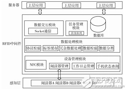
Figure 1 Overall architecture of the system
1) The device management module mainly consists of 4 parts. The NFC card reading part is responsible for calling the mobile phone's own NFC module to read the tag information; the external reader management part is compatible with the external reader driver, and is connected with Bluetooth, WiFi, 3G network, etc. Data interaction; the work log management part mainly manages the work log of the mobile phone and the middleware; the mobile phone status inquiry part can query the state of the mobile phone power, the remaining storage space, the signal and the like in real time.
2) The data processing module mainly consists of five parts. The protocol verification part is responsible for preliminary verification of the RFID tag data according to the identification bits to remove the missing or non-system data; the tag cache part uses the BlockingQueue queue as the cache to be initially verified. Data storage; redundant data processing part adopts adaptive Sorting Neighborhood Method (SNM) to remove redundant data; data verification part uses CRC16 algorithm to check the verification source data in tag data, Verify that the tag data has been tampered with; the data classification section classifies the data according to the agreed data rules.
3) The database module uses the SQLite embedded database to store the processed data.
4) The data interaction module uses the Quartz framework combined with Socket programming to implement data interaction between the middleware and the server.
5) The task management module is responsible for caching and managing the command files sent by the server.
1.2 System design focus
1.2.1 Device Management Module
The module is mainly for the management and monitoring of hardware devices, integrated NFC and external card reader drivers, and can query the system work log and mobile phone status.
The system mainly uses the NFC module to read and write RFID cards, integrates various NFC standards, and can automatically determine the card type. The relevant codes are as follows:
mTechLists = new String[][]{new String[]{MifareClassic.class.getName()},
New String[]{MifareUltralight.class.getName()},
New String[]{NdefFormatable.class.getName()},
New String[]{Ndef.class.getName()},
New String[]{IsoDep.class.getName()},
New String[]{NfcV.class.getName()},
New String[]{NfcF.class.getName()},
New String[]{NfcB.class.getName()},
New String[]{NfcA.class.getName()}};
In order to make the system have good scalability, the middleware is compatible with a variety of card reader drivers, and data transmission with an external card reader through Bluetooth, WiFi, 3G network, and the like.
In addition, it provides a good interface for real-time query and management of middleware work logs and information such as mobile phone power, signal strength, and remaining storage space.
1.2.2 Data Processing Module
1) Data buffering, verification and redundant data processing.
The system uses the BlockingQueue queue as a cache to store large amounts of data received in a short period of time. Perform preliminary verification of the received card data to remove missing or non-system data.
Table 1 shows the label data format, in which the UID is uniquely identified for each label. The first 7 bits in the check data are the original data used to generate the check code, and the 8th bit is the system label identifier, and the label is for each label. The 7-bit check data is generated by the CRC16 algorithm, and is written by the server to the mobile phone database through the JSON file along with the tag UID. After reading the tag data, the middleware first determines whether the card belongs to the system according to the eighth bit identifier in the check source data, and then generates the check code for the first 7 bits of check data by using the same CRC16 algorithm. And based on the label UID compared with the check code in the database, to determine whether the tag data is rewritten. The 8-bit check source data needs to be removed after the verification is completed, and only the useful data is stored.
Table 1 RFID tag data format

Data redundancy is an inevitable problem in RFID systems. If data is not cleaned, a large amount of useful and useless data will occupy network bandwidth and increase the processing load of the system; if the received data is compared with the data in the database one by one, although the accuracy rate High, but the system efficiency is reduced when facing a large amount of RFID data. Therefore, the system uses the SNM algorithm to process redundant data for the limited resources of the mobile terminal and the comprehensive consideration of data processing efficiency.
The data cleaning process is shown in Figure 2.
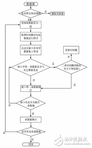
Figure 2 data cleaning flowchart
2) Data classification.
The data to be cleaned is classified according to the pre-agreed data rules. For example, if the Ni to Nj bits in the card are specified as data identification bits, the data is stored in the corresponding table of the SQLite database.
1.2.3 Data Interaction Module
The module is responsible for data interaction between the mobile middleware and the server, and improves the transmission speed under the premise of ensuring data integrity and security. Socket communication is used to transfer commands and data in the form of files. The CRC is used in the module to ensure file security, and file breakpoint uploading and downloading are supported. The related files are stored and backed up on the mobile terminal. Even if the network fails, the middleware can work normally without data loss.
The data interaction process is shown in Figure 3.
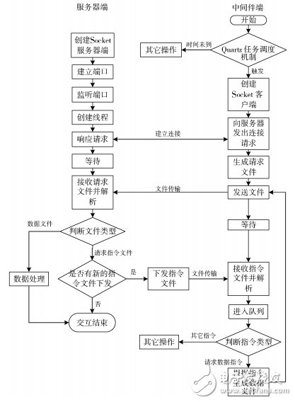
Figure 3 data interaction module flow chart
The middleware uses the Quartz open source framework to set the job schedule according to the requirements, and automatically sends a request to the server at a certain time. If the server has a new command, the command is obtained, parsed and executed without manual intervention, and the parameters can be sent by the server. The command is modified, the degree of automation is high, the configurability is good, and the server side uses the multi-threaded processing of the middleware request, thereby improving the processing efficiency.
Table 2 Data interaction module transmission speed test
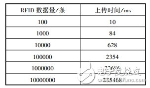
Table 2 shows the test results of the data interaction module transmission speed. The test data is the RFID tag data supporting the ISO15693 standard. The mobile terminal uploads the RFID tag data file to the server through the 3G network, supports file breakpoint retransmission, and when the file is transmitted. Once completed, it will also be backed up locally to avoid file data loss. Since the mobile phone side buffer is limited and tested, if the transmitted data packet is too large and the data is lost, the system data packet size is set to 1kB, and each time the data packet is sent, a header is added to identify the mobile phone and the trailer. Make a CRC check. When the amount of data is small, the transmission speed is greatly affected by the header and the trailer, and when the amount of data increases, the impact of the header and the trailer on the data transmission speed is less and less. Therefore, when the amount of data transmitted increases to a certain extent (about 100,000 data), the time consumed is basically proportional to the amount of data. In addition, the data transmission speed is greatly affected by network factors and device read/write speed.
1.2.4 Task Management Module
The command file is parsed and executed in sequence. If the command is executed successfully, the command file is moved to the backup folder. If the command fails to be executed due to network reasons, the command is added to the task queue. After the network is restored, the command is executed. The data required by the command is temporarily stored in the local database.
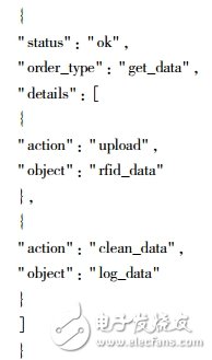
As shown in the following JSON command, status indicates the command status, that is, whether the server command is normal; order_type indicates the command type, such as obtaining data, modifying parameters, etc.; details indicates the detailed operation to be performed, where object indicates the operation object; acTIon Indicates the operations performed on the object, such as obtaining a certain type of data, obtaining a log file, obtaining the device status, or modifying program parameters such as request upload/download interval, so that the middleware is configurable.
1.2.5 Data Storage Module
The middleware generates a JSON file according to the command sent by the server, and sends the JSON file to the server. The data file in the JSON format is backed up to the local storage device to prevent the data received by the server from being caused by network problems. Complete, only the server receives the complete data, and sends the relevant commands to the middleware, the middleware can delete the relevant data files according to the command, thereby saving the storage space of the mobile device.
1.3 System advantages
1) Reduce the burden on the server.
The RFID raw data is processed through a plurality of middleware deployed on the mobile device, and the processed valid data is sent to the server end, thereby reducing the pressure on the server side, reducing the network transmission amount, and improving the system operation efficiency.
2) It has data storage and backup functions and is highly independent.
The storage performance of mobile devices is getting stronger and stronger. When the network or server fails, RFID data can be stored in the mobile device, effectively avoiding data loss. Therefore, it can work normally in the case of disconnected network, and solves the dependence of the previous RFID middleware technology on the network.
3) Flexible operation and simple deployment.
The NFC mobile phone integrates the card reader and the middleware, and can increase or decrease the number of devices according to the amount of data. It can also adjust the position of the middleware according to the card distribution, which is convenient for deployment, and also solves the problem of the card reader in the RFID system. Information security and transmission rate issues with middleware.
4) The system is highly configurable.
The middleware and the server end control the system to perform related operations or change system parameters by transmitting JSON commands, such as obtaining specified data, changing the data interaction time interval, and the like. At the same time, the operator can also set the middleware parameters through the system interface, which solves the shortcomings of low automation and poor configurability of the middleware.
5) Automatic alarm mechanism.
The system periodically performs self-test on device logs and status information. If an emergency situation occurs, such as insufficient power, excessive storage space, and tampering with card information, you can send warning information to the specified mobile phone number in time to avoid losses and make up for In the past, the middleware alarm was not timely.
2 system implementation and operation effect
The system is written in Java language based on Eclipse platform, the database is SQLite embedded database, the test device is Meizu MX3 smartphone, its RAM capacity is 2 GB, CPU frequency is 1638MHz, ROM is 32 GB, test card follows ISO15693 standard, adopts NFC The module reads the contents of the card, and part of the running interface is shown in Figure 4.
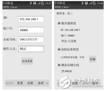
Figure 4 system operation part of the interface
When the program is running, connect the phone to the computer, start the Dalvik Debug Monitor Service (DDMS) in Eclipse, and check the system consumption memory through the Heap that comes with DDMS, showing that the program occupies 22.628 M of CPU. With an occupancy rate of 6%, it can be seen that the system works flawlessly in the limited resources of mobile devices. And tested, the SQLite database with 1000 W RFID data is 188 M. From the perspective of storage space, the RFID middleware can be deployed in most mainstream mobile devices, and can process and store more data efficiently. .
In order to simulate the working condition of the system under a large amount of RFID data, the program automatically generates test data according to the RFID data rules. The system performance test results of different data quantities are shown in Table 3.
Table 3 Middleware part performance test
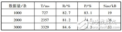
In Table 3, T represents the time required to clean the original data and store it in the database. R and P represent the recall rate and correct rate of data cleaning, respectively, R = the number of duplicate records correctly identified by the system / the number of duplicate records actually included in the data set , P = the number of duplicate records correctly recognized by the system / the total number of duplicate records retrieved by the system, and Size indicates the size of the database that holds the corresponding data volume.
It can be seen that the system can meet the basic data processing requirements, but the recall rate, correct rate and time spent on data cleaning need to be improved. The reason for the analysis is mainly the size of the sliding window and the selection of sort keywords. When the window is too small, it is easy to miss, that is, the redundancy is not good, and the recall rate is not ideal. When the window is too large, many unnecessary comparisons are generated, and the time effect is not satisfactory. So, use an adaptive random window to find a balance between the two. The key selected by the system is a timestamp, and according to the actual application, the newly arrived RFID data is more representative of the current situation, so the latest timestamp data is retained for each comparison, so that the time threshold between some data may be less than the pre- Setting values, that is, some data is mistaken for duplicate data, resulting in an accuracy that is not ideal.
3 Conclusion
This paper proposes an RFID middleware based on NFC mobile phone. Because the NFC mobile phone combines the functions of the card reader and the middleware, and has better storage capacity, the middleware can still run even in the event of network failure, and the system is deployed. More flexible; the data interaction module uses the Quartz framework combined with Socket programming, and has a high degree of automation; the parameters are set through JSON commands or a good interface, so that the system has good configurability; Alarm SMS for timely processing; make full use of the advantages of mobile Internet, the perfect combination of RFID middleware and mobile platform, to solve the many inconveniences of traditional middleware.
Offline communication activities: [The 3rd NFC/RFID Technology Application Forum] is about to kick off
Registration click ^
| About Paper Covered Wire. |
Paper Covered Wire includes NOMEX Coated Copper Wire, Paper Covered Flat Aluminium Wire, Paper Covered Flat Copper Wire.
Application: oil-immersed transformer windings
Using 100% oxygen free pole as extrusion raw material, insulation material using high density telephone paper, cable paper, polyester, non-woven fabric.Self-locking wrapping is adopted within 6 layers, the bending performance is 15% higher than the national standard, the temperature index is 105℃ after the phone paper and cable paper are impregnated, this product has excellent voltage resistance performance in oil, widely used in transformer coil, stable performance, short processing cycle.

As per Conductor Material:Copper , aluminum
As per Inner Conductor: Paper wrapped bare
Insulation thickness:Double paper covered (DPC) or Triple Paper Covered (TPC) ,According to Customer`s requirements
Paper Covered Wire
Insulated Wire Copper,Paper Covered Wire,Paper Covered Copper Flat Wire,Paper Covered Insulated Wire Copper
HENAN HUAYANG ELECTRICAL TECHNOLOGY GROUP CO.,LTD , https://www.huaonwire.com