cutting edge
The emergence of the Apple iPhone has made the concept of smart phones into thousands of households. With the rapid popularization of smart phones, consumers' demand for smart phone functions and experiences continues to increase, making smartphone manufacturers continually pursue high-configuration of hardware parameters. The most obvious is that the number of CPU cores and the screen size continue to increase. Recently, the domestic Huawei mobile phone has launched a 6.1-inch, quad-core 1.GHz CPU Mate smartphone, pushing the hardware parameters of the smartphone to another peak. However, the improvement of these two hardware parameters has seriously affected the consumer's demand for mobile phone standby time.
At the beginning of the year, US information company JD Power released the 2012 smartphone user satisfaction survey report, and the survey results also showed that the mobile phone battery is the bottleneck of the use of smart phones. The survey also showed that the power consumption of mobile phone batteries is one of the most important factors in determining whether customers are satisfied with mobile phones. A simple function machine, it is not uncommon to put it on for 10 days and a half after fully charged. But smartphones have to plug in the charger every day, just like going back to the wired phone era, there is always a "rope" to follow your phone. It is a pity that the breakthrough of lithium battery technology is far from keeping pace with the development of other hardware. The surge in power consumption of smart phones is pushing the mobile phone battery to an absolute bottleneck. In this case, if you want to work on the battery side, you can only increase the battery volume to increase the capacity. At present, the mainstream mobile phone battery capacity is between 1000-2000mAh. Large-sized machines will have mobile phones equipped with 2500mAh batteries, while Huawei's mate is equipped with 4050mAh batteries.
Large-capacity batteries inevitably bring long-term charging time, and at the same time put forward higher requirements for the charging technology of smart phones. This article mainly introduces the current mainstream smart phone charging scheme.
Passive discrete device solution
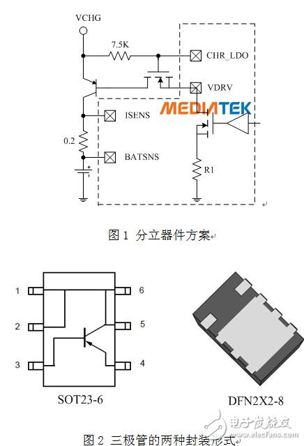
The discrete device charging scheme is mainly extended from the functional machine era. Figure 1 shows the MTK platform currently in the mainstream charging scheme of the functional machine platform and the low-end smartphone platform. The charging control is controlled by the main platform. The voltage difference of the 0.2 ohm resistor between the ISENS/BATSNS pins is detected by the two ADCs. The internal logic circuit sets the current flowing through the R1 resistor to control the charging current of the battery. And also through the 7.5K resistor and NMOS tube isolation BB or PMU directly face the pulse high voltage impact of the VCHG charger output, to ensure that the main chip will not be burned out due to the high voltage output of the inferior adapter.
The advantage of the discrete device charging scheme is that the cost is cheap enough. The disadvantage is that the charging current is relatively small. The current mainstream setting is 500 mA, and the charging protection mechanism is mainly realized by the platform's own software and hardware. The advantages and disadvantages of discrete device charging schemes are obvious, but in the era of functional machines, the advantages of discrete devices have been greatly promoted, and the disadvantage of less charging current has not brought a poor experience to consumers in the era of functional machines. Because of this, the discrete device charging solution has become the mainstream charging solution for all functional machine platforms.
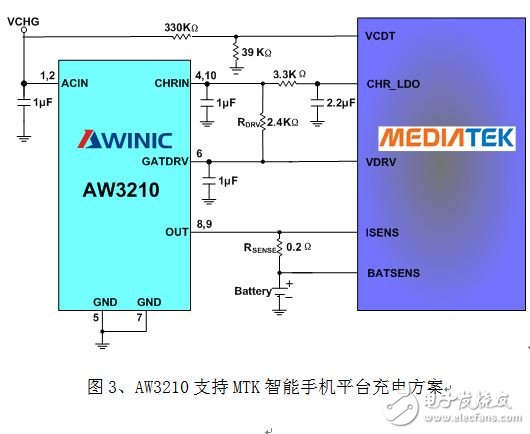
However, as the battery capacity of smart phones continues to increase, the disadvantages of less charging current of discrete devices continue to emerge. Because of cost considerations, many manufacturers want to increase the charging current by means of discrete devices. However, discrete devices are difficult to achieve large current charging due to poor heat dissipation. Figure 2 is a package diagram of the triode in the high current path of the circuit of Figure 1, from the early SOT23-6 package to the DFN2X2 to support higher current charging. -8 package, but the structure of the discrete device itself can only dissipate heat through the pin, which limits the heat dissipation effect of any package. Similar active power devices are packaged in DFN and QFN. It is possible to use the heat sink at the bottom of the package. This heat sink must have a good heat dissipation effect and must be connected to the ground of the motherboard. Passive discrete devices have no way to use heat. This effective cooling function of the disc.
Active linear charging scheme
When the mobile phone platform is not highly integrated, active linear charging is the mainstream solution for mobile phone charging. Later, with the continuous integration of the platform, BB integrates the charging control logic into its own PMU, considering the heat dissipation. A tube that requires excessive current is placed outside, extending the charging scheme of the discrete device. With the increasing popularity of smartphones, battery capacity continues to increase, and the demand for charging current continues to increase. The discrete device described above has a problem of small charging current and poor heat dissipation. The integrated solution for linear charging has begun to be adopted by some manufacturers who pay more attention to quality.
The advantages of active linear charging are: 1. The chip integrates more charging protection mechanism. This protection mechanism is more and more concerned by engineers as the charging current increases. After all, the charging module will involve the reliability of the mobile phone. 2, better heat dissipation, active charging ICs generally use DFN/QFN package with heat sink, the ground inside the chip will be connected to the ground of the motherboard through the package heat sink, which is very beneficial to the heat dissipation of the motherboard. There is a situation where the temperature of a local area of ​​the mobile phone motherboard is too high. The disadvantages are: 1. The cost is higher than the passive discrete device scheme; 2. The maximum charging current is supported to 1A, the current is large, and the heat dissipation problem caused by low efficiency is also apparent.
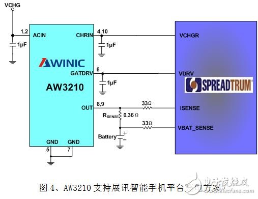
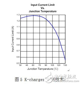
As shown in Figure 3 and Figure 4, the AW3210 supports a cost-effective charging solution for MTK and Spreadtrum smartphone platform 1A charging. In addition to linear protection conventional protection mechanisms such as OVP, OCP, and soft-start protection, the AW3210 also features a patented K-charger developed for high-current charging. The patented K-charger technology automatically adjusts the charging current based on the temperature of the chip. Size, to avoid the reliability of charging due to misuse during use. Figure 5 is a graphical representation of the K-charger technology charging current followed by chip temperature changes.
FTTH Fiber Optic Splice Tray is designed to provide a place to store the fiber cables and splices and prevent them from becoming damaged or being misplaced. It is also called a splice enclosure or splice organizer. This device does not contain any technical functions, and the design is simple. Also, Fiber Optic Tray has a very low price for people to afford. However, the importance of fiber splice tray for protecting fibers is significant. And the skills needed for using a fiber splice tray is not as simple as you think.
Made by industrial high-quality ABS plastic, Fiber Optic Cable Tray is provided to place the fiber splice points and pre-terminated for fiber connectivity. The splice tray expands fiber splice capabilities as well as provides the splicing location for fiber optic cables. It can be put into the fiber distribution frame, fiber splice closure, optic terminal box, etc. Sijee offers different shapes of fiber splice tray with or without termination function. Fiber Optic Tray, Fusion Splice Box, Fiber Optic Cable Tray, Splice Tray Optic Fiber are available.
Applications:
Fiber splice trays are usually placed in the middle of a route where cables are required to be joined or at the termination and patch panel points at the end of the cable runs. Also, splices can be placed in a splice tray which is then placed inside a splice closure for OSP (outside plant) installations or a patch panel box for premises applications. As for indoor application, fiber splice trays are often integrated into patch panels to provide for connections to the fibers.


Fiber Optic Tray,Fusion Splice Box,Fiber Optic Cable Tray,Splice Tray Optic Fiber
Ningbo Bwinners Optical Tech Co., Ltd , https://www.sijee-optical.com