The crystal resonator is one of the important components for generating a reference clock signal of an integrated circuit such as a microcomputer (microcomputer), and is widely used from information communication terminals such as mobile phones and smart phones to automobiles and household appliances. Among them, in particular, in the use of information communication terminals, the demand for miniaturization of components is strong, which poses a problem for component design - maintaining product characteristics while reducing its size. We introduce a method here, the core of which is the application of the finite element method (FEM) simulation technique, which can be used efficiently and efficiently.
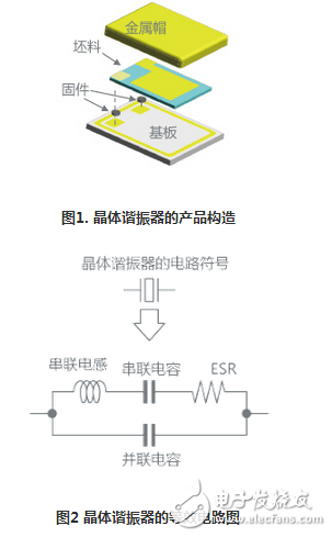
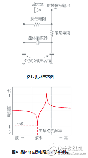
1. AT-cut crystal resonator and oscillator circuitThe AT-cut crystal resonator is an element that uses an artificial quartz crystal as a material and utilizes piezoelectric characteristics (thickness shear vibration). The representative product structure of Murata is shown in Fig. 1, and the equivalent circuit is shown in Fig. 2. This component is one of the important components constituting an oscillating circuit that issues a reference clock signal necessary for the operation of the microcomputer. In addition, we represent a representative configuration of the oscillating circuit as shown in FIG. The oscillating circuit issues a clock signal by means of an amplifier that amplifies the electrical signal passing through the crystal resonator. The crystal resonator is shown in Figure 4. The resistance value varies depending on the frequency. At this time, the main vibration frequency resistance value of the blank (crystal blank) is the smallest, and this resistance value is called ESR. The oscillating circuit oscillates around the main vibration frequency of the blank and outputs a clock signal.
An important point of the oscillating circuit is that the oscillation is stable. One of the indicators is the oscillation margin, which shows how much signal amplification is possible for parts other than the crystal resonator in the circuit for ESR (an important cause of signal attenuation). In theory, the oscillation margin is >1, and the circuit will oscillate, but occasionally it will not oscillate when it is nearly 1 times, and the oscillation start time is abnormally long, which causes the device where the circuit is located to be unable to work normally. Suppressing ESR can improve the oscillation margin, but usually the lower the frequency, the higher the ESR, and the lower the product size, the higher the ESR. Information terminals and the like are currently using 2016 and 1612 size products, and the market demand is smaller, so the design has become very difficult recently.
2. Key points of feature design
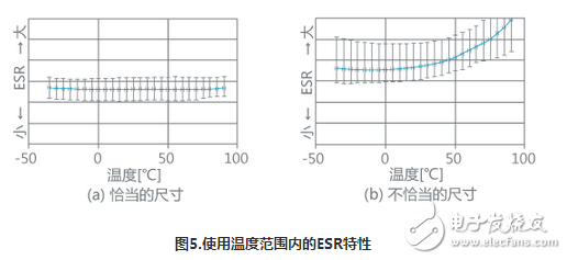
In addition to the thickness shear vibration used as the main vibration, there are many unnecessary vibrations in the AT-cut crystal resonator. When designing a crystal resonator, it is necessary to consider how to determine the geometric parameters while not allowing these unnecessary vibrations to affect the operation within the operating temperature range. Figure 5 shows the relationship between temperature and ESR, comparing the design (a) with the right geometry selected and the design (b) with the incorrect geometry selected. When inappropriate geometric parameters are selected, unnecessary vibrations are superimposed and the ESR value increases. In the design phase, it is critical to choose geometric parameters that are unaffected by unwanted vibrations. However, the number of geometric parameter combinations is large, and many times it is necessary to repeatedly experiment and find out the optimal solution. This has become one of the reasons hindering shortening of development and difficulty in improving quality.
3. Applications and topics of simulation (finite element method: FEM)
As a means to efficiently find the optimal solution, the finite element method (FEM) can be considered for characteristic simulation. However, there is a problem with this method, that is, the consistency between the simulation result and the real sample characteristics is low. We have found the reason – not only the geometry, but also the firmware that connects the blank to the substrate to the main vibration (thickness shear vibration) and the frequency of unwanted vibrations.
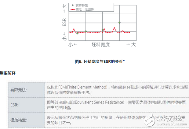
Figure 6 shows a comparison of the FEM simulation results with the actual sample characteristics when the firmware on the substrate is only molded into the blank. In the simulation of the results without the firmware shape, the tendency of the ESR characteristic is inconsistent with the actual sample characteristics, and the proper geometric parameters cannot be found.
As shown above, it has been our subject to establish simulation techniques to improve the consistency of simulation results and sample characteristics, and to efficiently find optimal solutions. This time, by constructing a simulation system that can solve these problems, we have been able to improve the consistency of the simulation results and the real sample characteristics.
For diifferent USB types, micro USB, mini USB, etc. The logo, color or shape can all made as customers' requirement. With more than ten years of experience and capabilities assisting our customers in various industry, ETOP would be confident to be your qualified AVL and reliable manufacturing partner.
Related Products:usb cable,micro usb cable,usb data cable.
Data Cable,Data Flexible Electrical Magnetic Cable,Usb Data Cable,Micro Usb Cable,USB Connector
ETOP WIREHARNESS LIMITED , https://www.etopwireharness.com