A microphone preamplifier circuit is used to amplify the output signal of the microphone to match the input level of subsequent devices in the signal link. Matching the peak value of the microphone signal level to the full-scale input voltage of the ADC maximizes the dynamic range of the ADC and reduces the signal noise that can be caused by subsequent processing.
A single operational amplifier can simply be applied to the circuit as a preamplifier for the MEMS microphone output. The MEMS microphone is a single-ended output device, so a single op amp stage can be used to add gain to the microphone signal or just to buffer the output.
This application note contains key elements of the op amp specifications that need to be considered when designing the preamplifier, shows some of the basic circuits, and provides a list of ADI's op amp products for use in preamplifier designs. This application note uses the ADMP504 MEMS microphone as an example to illustrate the different design options. The microphone is an analog microphone with a signal-to-noise ratio (SNR) of 65 dB. When using a different microphone design, the requirements may differ from those described in this application note, and need to be adjusted based on the microphone's noise, sensitivity, maximum acoustic input, and other specifications.
Operational amplifier specifications
Op amps come in many different specifications and performance curves, so finding the specifications associated with your application can be a tedious task. For mic preamp designs, some specifications are more important than others; this application note outlines this part of the specification.
noise
The noise value of an operational amplifier is divided into voltage noise and current noise. In general, you only need to consider the op amp's voltage noise in the design of the preamplifier. Current noise needs to be considered in the design only when using high value (ie high noise) resistors. In order to maintain the overall noise of the circuit at a low level, resistors below 10 kΩ are typically used.
The voltage noise of the op amp is defined in terms of noise density in nV/√Hz. For device noise associated with circuit bandwidth, you need to multiply this noise density by the square root of the bandwidth. Please note that this simple formula only applies to the uniform noise spectrum over the frequency range, as shown in Figure 1.
For a bandwidth of 20 kHz, the multiplier factor is 141. Taking the ADA4075-2 as an example, the noise density is 2.8 nV/√Hz multiplied by 141, so the noise level is 0.395μV or -128 dBV. The noise density of an op amp is usually shown in a table in the Typical Characteristics section of the data sheet and usually shows the curve over its entire frequency range. This chart can be used to see at what frequency the op amp noise will depend on the 1/f noise. For many op amps, this point is usually lower than the audio band (20 Hz) low end, but the noise density curve is still worth looking at, and the noise performance cannot be fully described with reference to the noise density index alone. Figure 1 shows an example of a noise density map in the ADA4075-2 data sheet. Note that the 1/f turning point in Figure 1 is approximately 10 Hz, which is much lower than the target frequency band of the MEMS microphone preamplifier circuit.
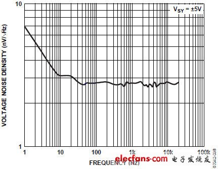
Figure 1. ADA4075-2 voltage noise density
The ADMP504 analog MEMS microphone has an SNR (A-weighted) of 65 dB and a sensitivity of -38 dBV. Therefore, the noise floor is -103 dBV in the 20 kHz bandwidth. This is equivalent to a noise density of 50 nV/√Hz, which is about the same as the thermal noise of a 150 kΩ resistor.
For op amps, it is important to have a lower noise than the microphone, so the noise of the preamplifier circuit should be as transparent as possible. A very good practice is that the op amp's noise is at least 10 dB lower than the microphone itself to minimize its effect on global noise. To achieve this with the ADMP504 preamplifier, the op amp's highest noise floor is -113 dBV or 15.9 nV/√Hz. Most of the op amps in Table 1 are well below this limit, and op amps that are not below this limit are still listed because they have other parameters that may be important in some special designs, such as for low The operating current of the power design. Note that the total output noise level of the circuit will be affected by the applied gain and the resistance in the circuit, not just the op amp. You can minimize the effect on total circuit noise by choosing a resistor that is small enough.
Slew rate
The slew rate of an op amp refers to how fast the output voltage changes (or swings) from one voltage value to another. The unit of this parameter is usually V/μs. The highest slew rate that the preamplifier circuit must support
SR = 2 &TImes;Ï€&TImes; fMAX&TImes; VP
Where fMAX is the highest frequency that the preamplifier needs to support (the audio is typically 20kHz) and VP is the peak voltage level of the op amp output. If the peak output voltage is +12 V (8.5 VRMS), the op amp has a slew rate of at least 1.5 V/μs.
In fact, most audio signals do not reach full-scale voltage in the high frequency region, but this possibility should be considered when designing the preamplifier. Usually the slew rate index in circuit design should not be designed too high. In the design you can use an op amp with a fast enough slew rate to handle the highest target frequency, but there is no need to raise this limit too much.
Total harmonic distortion plus noise (THD + N)
A discussion of total harmonic distortion plus noise (THD + N) in an op amp circuit can easily become a complicated discussion. There are many reasons that can cause distortion, including slew rate limitations, output loads, and internal distortion characteristics of the op amp. THD is usually defined as a ratio expressed as a percentage or as a dB value. This ratio is the ratio of the amplitude of the harmonic distortion portion of the letter to the amplitude of the input fundamental frequency, so the smaller the value (small percentage value or negative dB value), the better its THD + N performance.
The THD + N parameter is the sum of the specified bandwidth noise and THD. This value is not included in the specification table for all op amp data sheets. Even if there is no change, the data sheet will usually contain a plot of THD (or THD+N) versus frequency. Figure 2 shows an example of this value in the ADA4075-2 data sheet.
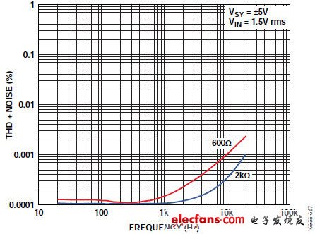
Figure 2. ADA4075-2 THD + N vs. Frequency
A portable power station is the best option if you need to juice up common personal electronics and small appliances while spending long periods of time away from household AC outlets, or if you want to have backup power ready to go in case of an emergency.
They have enough capacity to power a few small appliances for a short time. With a host of different outlets (standard 120v outlets, USB ports, and DC chargers), you can use the station to charge electronics, too. And the units often come with portable solar panels, to add more charging capabilities and extend runtime.
UPGRADED 250-WATT POWERFUL AC, USB AND 12V OUTPUTS: Comparing to similar Battery powered generators, Rockpals RP250W portable generator has upgraded the AC output to 250W continuous (300W surge max) dual AC outputs, built-in 2x USB 2.1A and 4x DC 12V ( 60W ) ports. Perfect emergency backup power for home/ travel/ camping, charging up your tablets, iPhone, iPad, laptops, fans, TV, lights and CPAP machine (*Use DC converter from your CPAP would get longer hours)
Portable Power Station,Portable power, Off-grid Power Supply, Portable Generator, Backup Camping Emergency,Backup Lithium Battery for Outdoor
Wuxi Sunket New Energy Technology Co.,Ltd , https://www.sunketsolar.com