1. General requirements for LED drivers
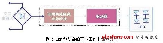
The arrangement of LEDs and the specification of LED light sources determine the basic driver requirements. The main function of the LED driver is to limit the current flowing through the LED under a certain range of operating conditions, regardless of changes in the input and output voltages. The schematic diagram of the basic working circuit of the LED driver is shown in Figure 1, where the so-called "isolation" means that there is no physical electrical connection between the AC line voltage and the LED (that is, the input and output). "Non-isolated" does not use high-frequency transformers for electrical isolation.
It is worth mentioning that in the LED lighting design, the two parts of the AC-DC power conversion and constant current drive circuits can be used in different configurations:
(1) Integral configuration, that is, the two are fused together and are located in the lighting fixture. The advantages of this configuration include optimized energy efficiency and simplified installation;
(2) Distributed (distributed) configuration, that is, the two exist separately. This configuration simplifies security considerations and increases flexibility.
Second, how to choose the LED drive method
Today's typical LED drivers on the market include two types, namely linear drivers and switching drivers; the approximate scope of application is shown in Figure 2. If high-current applications with currents greater than 500mA use switching regulators, because linear drivers are limited to their own structural reasons, they cannot Provide such a large current; and in low current applications where the current is less than 200mA, a linear regulator or a split regulator is usually used; and in medium current applications from 200 to 500mA, both a linear regulator and a A switching regulator can be used.
The switching regulator has high energy efficiency and provides excellent brightness control. The linear regulator has a simple structure, is easy to design, provides steady current and overcurrent protection, and has no electromagnetic compatibility (EMC) issues.

In low current LED applications, despite the low cost and simple structure of the resistive driver, this driver has a low forward current under low voltage conditions, which will result in insufficient LED brightness and under transient conditions such as load dump. , The LED may be damaged; and the resistance is an energy-consuming element, the energy efficiency of the entire scheme is low, see Figure 3.
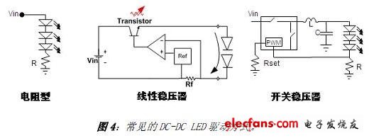
For example, in LED lighting applications that use DC-DC power supplies, the LED drive methods that can be used are resistive, linear regulators, and switching regulators. The basic application diagram is shown in Figure 4.

In the resistive drive method, the forward current of the LED can be controlled by adjusting the current detection resistor in series with the LED. This drive method is easy to design, low in cost, and has no electromagnetic compatibility (EMC) problems. The disadvantage is that it depends on voltage and requires screening (Binning) LED, and low energy efficiency.
Linear regulators are also easy to design and have no EMC issues. They also support current stabilization and overcurrent protection (fold back), and provide external current setpoints, which is insufficient for power dissipation issues, and the input voltage must always be higher than the forward Voltage, and energy efficiency is not high. The switching regulator continuously controls the on and off of the switch (FET) through the PWM control module, thereby controlling the flow of current.
The switching regulator has higher energy efficiency, has nothing to do with the voltage, and can control the brightness. The disadvantage is that the cost is relatively high, the complexity is also higher, and there are electromagnetic interference (EMI) problems. Common topologies of LED DC-DC switching regulators include different types such as Buck, Boost, Buck-Boost, or Single-Ended Primary Inductance Converter (SEPIC).
Among them, the step-down structure is adopted when the minimum input voltage is greater than the maximum voltage of the LED string under all operating conditions. For example, 24 Vdc is used to drive 6 LEDs in series; in contrast, the maximum input voltage under all operating conditions is less than the minimum output voltage. Boost structure, such as using 12 Vdc to drive 6 LEDs in series; when the input voltage and output voltage range overlap, buck-boost or SEPIC structure can be used, such as using 12 Vdc or 12 Vac to drive 4 LEDs in series However, the cost and energy efficiency of this structure are the most unsatisfactory.
Shenzhen Linx Technology Co., Ltd. , https://www.linxheadphone.com