Design and Implementation of Monitoring Network System Based on Distributed Components
With the increasing development of monitoring technology towards automation, intelligence and networking, the monitoring management is becoming more and more complicated, and the monitoring system is continuously given new content and organizational forms, thus putting forward higher requirements on the monitoring system. This paper designs and implements a monitoring network system based on distributed component technology, which can realize various real-time monitoring and non-real-time monitoring functions, has good scalability, and is actually used in the national shortwave monitoring system. The modern monitoring network system consists of a complete set of signal detection, transmission, analysis, control and display systems. It is equipped with advanced monitoring equipment and corresponding control and automatic monitoring software, and is interconnected through computers and networks.
1 System design principles
In order to improve system response performance and stability, enhance code reusability, scalability and easy maintenance, to meet the changing needs of users to the greatest extent, the design principles of the entire monitoring network system are: based on distributed component design; based on three Layer structure pattern design: Separate device driver from network monitoring software; separate data flow from business process; design based on network structure; design based on standardized module.
Each part of the software designed based on the distributed component (DCOM) is a program that runs independently and can run on different computers. In this way, each software function and each device can be completely independent.
Based on the three-layer structure mode design, the device driver is separated from the network monitoring software, so that each part completes its own function, and the coupling degree of each part is reduced as much as possible. Separating the data flow from the business process can simplify the logical complexity of the business process, thereby reducing the difficulty of software development and improving the efficiency of software development.
The equipment in the monitoring network is managed in a tree structure according to different monitoring centers and monitoring stations, which can not only manage users, devices, and functions in a unified manner, but also avoid network data bottlenecks caused by unified management.
Based on the standardized module design, each functional module is allowed to run independently, and one module dies without affecting other unrelated modules.
2 System architecture
2.1 Composition of monitoring system
The monitoring network system can measure various signals such as temperature, flow, pressure, and radio through various measurement equipment, and transmit the collected data to the monitoring centers and monitoring stations at all levels through the network, and analyze and analyze the data. Processing, timely and accurately feedback the signal measurement to the monitoring personnel, so as to monitor the operating situation, make timely treatment of the abnormal situation, and guide the decision.
The entire monitoring network system consists of the monitoring center, monitoring stations at all levels and the monitoring equipment under the monitoring stations through networking. The monitoring center is responsible for controlling each monitoring station and issuing monitoring tasks. It is the center for collecting and processing data. It is composed of controllers, routers, hubs / switches, network adapters, MODEM, and corresponding monitoring software. It can grasp the entire monitoring network in real time. Operating status. The monitoring station at least includes a monitoring server, a database server and several monitoring equipments. It can accept the measurement tasks of the monitoring center, realize automatic real-time and non-real-time monitoring of the measurement signals, analyze and display them, and send the data to the monitoring center. The monitoring station can also be made into a mobile in-vehicle system, which can be connected to the monitoring system through a wireless network to complete various monitoring tasks flexibly and flexibly. Various monitoring equipment under the monitoring station realize specific monitoring functions.
The monitoring center, monitoring stations at all levels and monitoring equipment form a local area network, which manages the tree structure, realizes various monitoring functions, and achieves the purposes of unified management, division of labor, cooperation, and data sharing. The data communication inside the monitoring station is directly completed through distributed components, and the data communication between each monitoring station is realized through the network communication service program for point-to-point communication (PPP), which can avoid the unified management of network equipment. Bottleneck of data transmission. According to the actual situation, users can build a small-scale monitoring network system with only one monitoring station or expand it into a national monitoring network system.
2.2 System software structure
The entire monitoring network system is based on distributed component design and adopts the three-layer structure form of "client-middle layer-device bottom layer". The client is the functional interface program of the monitoring system, which mainly completes the interaction function with the user; the middle layer is the core component of the project, which is mainly responsible for the distribution of commands and data, and the unified management of the device and the user; the underlying equipment is packaged into a component form, which is mainly completed The user's measurement task and return data. Figure 1 is a structural diagram of the overall framework of the monitoring system.
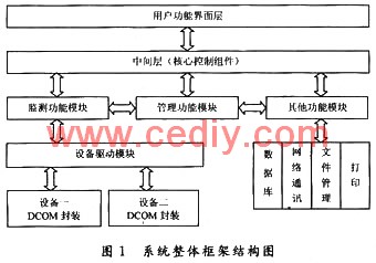
The client program is functionally a user-oriented window. There are two main functions: as a window for user and device interaction, sending commands to the middle layer and displaying the data returned by the middle layer; completing some independent of the middle layer Data processing function.
The middle layer is like the central nervous system of the entire system. It mainly completes two major functions: one is responsible for the management of the data flow of the entire system, upwardly accepts the measurement commands and parameters input by the client, and returns the corresponding measurement data and status to the client. Next, the measurement commands and parameters are sent to the underlying device, and the data returned by the device is accepted. The second is device management and user management. Simply put, it is unified management of devices and users in the network.
The bottom layer of the device is mainly the DCOM package of the device and the interface program with the middle layer.
3 Overall system design
3.1 Client programming
How to design a monitoring software with friendly interface, stable operation and quick real-time response is the primary requirement of the monitoring network system. The interactive interface and functions of the monitoring network system application software directly reflect the needs of users.
In the system design, a modular design based on distributed component design is adopted: each function is designed as a relatively independent functional module, and each part of the module is an independently running program. Call each other. This requires each module to have its own independent parameters, variables, and procedures; the functions of each module are not repeated, and each business function can be called repeatedly. The advantages of modular design: it is conducive to the development division of labor, reducing program overhead, and improving the efficiency of code use.
The user function interface is mainly composed of user login module, task management module, command control module, measurement parameter setting module, monitoring data display and analysis module. Each independent module makes full use of the idea of ​​object-oriented classes to develop and design. In the program development phase, each functional module is developed and tested separately to implement and improve various specific functions. When the overall planning is carried out, just like building a house, one module after another is called to form a beautiful, practical and freely deformable "house".
3.2 Design of the middle layer
The middle layer is the core control layer of the entire system, which is mainly responsible for the management of command data flow, device management and user management. The management of data flow includes: data distribution and management, command queuing management and distribution, and data distribution and management.
The main data flow is the data request process:
(1) Select the measurement parameters through the parameter panel, select the function operation through the command panel, compile the command directly into a binary stream recognized by the device and can be directly operated, and submit it to the network communication service program;
(2) The network communication service program transmits the data to the corresponding monitoring station data management service program (added to the middle layer queue);
(3) The data management service program sends the command data stream to the corresponding monitoring device driver service program;
(4) The monitoring results obtained by the equipment are returned to the data management service program;
(5) The data management service program automatically converts the monitoring result data into a standard data format and submits it to the network communication service program;
(6) The network communication service program returns the result data to the user interface;
(7) The user interface displays the data or saves it to the database through the storage process.
The entire data request process is similar to the "write letter → send letter → reply letter" process. First, the user interface writes "letters and envelopes" in the format recognized by the device, and then "sends" to the device through the middle layer. The middle layer converts the "reply" of the device into a standard format and returns it to the user interface.
3.3 Device bottom design
The bottom equipment is packaged in the form of DCOM, and each equipment operates independently. Once the device has an unexpected problem, it will crash or disconnect from the network, etc., which will not affect the work of other devices. The development of the bottom layer of the device mainly includes two parts: the DLL interface program between the device and the middle layer; the DCOM package of the device. The interface program between the device and the middle layer: when a new device is added, the middle layer program does not need to be compiled, and only the new device information needs to be added to the bottom layer DLL; the bottom layer DLL is responsible for translating the upper layer commands into the command format recognized by the lower layer DCOM.
The entire system software is divided into five parts, namely:
(1) User interface, he is a thin client and can be installed on any computer that needs to be monitored.
(2) Log in to the service program and install it on the monitoring server of the monitoring center.
(3) The data flow management program can also be called the middle layer. Including data management service program and state management service program, installed on the monitoring server of the monitoring station.
(4) Device driver service program.
(5) The network communication service program is installed on any computer that needs remote access.
Based on the design of distributed components, each part of the software can be encapsulated completely independently, forming a program that can run independently, so that each part of the software can run on different computers. In this way, the startup time of the device can be shortened, the operating efficiency of the device can be improved, the CPU usage can be reduced, and each software function and each device can be completely independent.
4 System test
Software testing is the key to ensuring software quality and improving software reliability. Let's test and demonstrate by setting up a single-frequency direction-finding monitoring system in the national short-wave monitoring system as an example.
The radio short-wave single-frequency direction-finding system is composed of monitoring servers and receivers under the monitoring station, and direction-finding devices and other monitoring equipment connected to the network. It can monitor and measure the short-wave signal, and can also be combined through several monitoring stations Time domain direction measurement and statistical analysis of a single radio signal. Since each part of the monitoring network system software is packaged in a standardized module form, each part of it can be independently tested, including software functions and performance indicators, so that each part of the system can be measured and controlled.
Therefore, in the software development process of the monitoring system, independent unit tests can be carried out on each completed module. After the developer writes the code and encapsulates it into an independent functional module, he can write a simple test program specifically for this module, which mainly tests the specific functions realized by each interface of the module. Finally, by calling each functional module to form the entire monitoring system, the overall function and performance test is carried out. Each module of the software based on distributed component design is an independent running program. For the module that has been developed and passed the test, when the system integration test is carried out, this module only needs to be installed, and no source code is required, which reduces software repeated development. The possibility of improving code security.

Figure 2 is the monitoring interface display of the radio shortwave single frequency direction finding monitoring system. Start a monitoring and testing process: First, the user logs into the system, selects the direction-finding device and direction-finding function in the monitoring station, starts the measurement, and calls the direction-finding function interface module. As shown in Figure 2, set the measurement parameters on the parameter input panel, click the start measurement button to send a "start measurement" command to the device, and the received monitoring data will be displayed on the interface through analysis and processing. You can also save data and print files by calling databases, files, and print modules. In addition, it is possible to start a single measurement task or multiple different measurement tasks without affecting each other.
Tests show that the entire monitoring network system is simple, practical and easy to operate; setting monitoring task types, setting measurement parameters, running and closing programs are very simple and fast; it can realize real-time monitoring and non-real-time monitoring functions; the entire system responds quickly and runs stable.
5 Conclusion
This paper designs and implements a safe, reliable, independent, and easily expandable monitoring network system based on distributed component technology and modularity. During the development and testing of the entire monitoring system software, the design idea based on standard modular and distributed component technology helps the software achieve weak coupling decomposition from the structure, which can greatly improve the independence, reusability and maintainability of the code It can easily realize the function expansion of the system, and can realize the development of functional modules on different language platforms, thus making the parallel development process easier and more efficient. The entire monitoring network system is designed to be practical and easy to operate; the monitoring function is perfect and has good scalability; the system runs quickly and stably, and is applied to the national short-wave monitoring network system.
CE Certificate Extension Sockets
Usb Electrical Outlet,Standard Wall Outlet,Legrand Usb Wall Socket,Remote Control Wall Plugs
Heikki Technology Co., Ltd. , https://www.heikkipower.com