According to the system requirements, the pulse radar altimeter outputs the altitude data through RS-422 serially, and requires the data receiving module to receive in real time and display the radar height data. The height data received by the receiving module is represented by a binary (BIN) code, and the display device such as a digital tube requires a BCD code (ie, a binary coded decimal code), so conversion between the two is necessary.
Compared with the conversion of BCD code and BIN code, the traditional method is realized by using DAA adjustment instruction, which needs to be adjusted bit by bit, which is time consuming. Literature [3] proposes to use modular division, each time moving nibbles, so that the conversion efficiency is greatly improved, but it is only a software algorithm, which can not meet the requirements of high efficiency and real-time performance of digital system conversion. Literature [4] proposed a hardware method using segmentation search EPROM to meet the real-time requirements of dot matrix recording, but the algorithm requires a large-capacity EPROM. The literature [5] uses the logical correspondence between the BCD code and the BIN code to directly convert, which requires multiple stages of complex transformation logic, and the area and delay are poor.
To this end, this article uses the Verilog HDL hardware description language to integrate the core functions of radar height data reception/display into XILINX's FPGA (XCS200), making the entire design more compact, compact, stable and reliable. Using the non-recovery residual array division to quickly and accurately convert the BIN code to the BCD code, only a small amount of shift and add/subtract operations are required, simplifying the remainder and divisibility operations in the digital system conversion. The cell array structure is regular, which not only saves area, but also is suitable for the implementation of VLSI, and is easy to expand to a higher hexadecimal, and has a high conversion speed.
1 Introduction to serial height data receiving/display module
The digital automatic distance tracking pulse radar altimeter serial output height data, first through the serial height data receiving module to convert the serial data into parallel message data, and then through the message filtering / data extraction module, extract the height data, And the working state of the radar is identified according to the time interval of the output height data, and then the height data represented by the BIN code is converted into a 90BCD code suitable for the seven-segment code display by the BIN/BCD code conversion module based on the division without restoring the remainder array. To scan the seven-segment code display controller to drive the four-digit seven-segment common anode dynamic display digital tube, as shown in Figure 1.

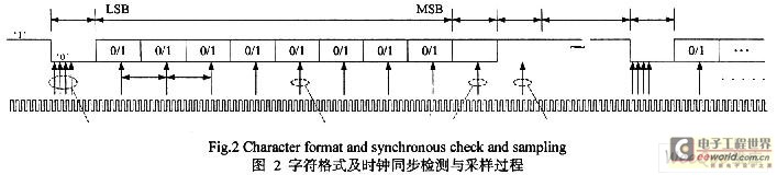
The serial height data transceiver module adopts three-wire connection mode, the communication mode is asynchronous transmission, baud rate: 9 600, data bit: 8 bits, stop bit: 1 bit, odd parity, its character format and clock synchronization detection and sampling The process is shown in Figure 2.
2 Conversion based on binary to BCD code without restoring remainder array division
The proposed conversion algorithm of BIN code to BCD code uses data divided by bit weight to obtain thousands, hundred, ten, and ones BCD codes, so the design of the divider is the key. Various divisions in numerical calculations can be described by the following recursive formula:
(1)
Here _j=0,1,...,n-1 is a recursive subscript; D is a divisor; qj+1 is the j+1th quotient to the right of the decimal point; r is the base, r×R(j) is the partial dividend; R (j+1) is a partial remainder; R(0) is the dividend (initial part remainder); R(n) is the last remainder.
The division process can be proved by repeatedly applying recursion formula 1.
For j=0
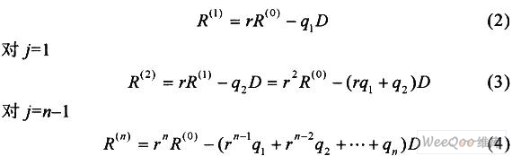
The above iterative derivation process shows that the division process consists of a series of addition, subtraction or shift, for the base r=2, q...∈{0,1}.
When the partial dividend rR(j) is insufficient for the divisor D to decrease, the quotient qj+1 is 0, and the next digit of the dividend is added, and the larger part is divided by the divisor; if it is sufficiently reduced, the digit quotient is 1, and the partial dividend is rR (j) The subtraction number D is subtracted, and then the next digit of the dividend is added until each digit of the dividend is used.
During the division process, a special data comparator can be used to compare whether the partial dividend rR(j) is larger than the divisor D (nonperforming algorithm), or directly subtract the number by the partial dividend. Mode 1 wastes a special data comparison circuit, which increases the operation delay and reduces the operation speed. Mode 2, when the subtraction operation is completed, if it is not enough, add the divisor back to the generated difference to restore the original remainder (recovery remainder method); or leave the generated difference to the next operation and then reprocess (do not recover the remainder) law).
2.1 does not restore the remainder array divider
For the sake of simplicity, the remainder is denoted by A, D represents the divisor, and R represents the remainder. In the recovery remainder method, if the remainder R is negative, that is, not enough, the divisor D needs to be added to restore the original remainder, that is, R+D. Then, the remainder R and the dividend A are jointly shifted left by 1 bit. The remainder is 2(R+D)+ai, where ai is a bit in A and is moved into R. Then, proceed to the next step. That is, subtract the number D from the remainder: (2(R+D)+ai)-D, there is
(2(R+D)+ai)-D=2R+ai+D (5)
Therefore, when the remainder R is negative in a certain step, it is not necessary to add the divisor D to restore the original remainder, and only need to change the subtraction number D in the recovery remainder method to the divisor D in the next step. The algorithm is called the non-recovery remainder method. The recovery remainder division requires 2 steps to determine 1 quotient, without restoring the remainder method without this disadvantage.

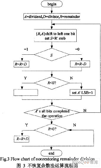
Table 1 uses 45 10/1010=101101 2/10102 as an example of numerical calculation, and shows in detail the flow chart of the non-recovery remainder method shown in Fig. 3. First, the remainder and the dividend A are jointly shifted left by one. If the sign bit S of the remainder R is 0, the subtraction operation will be performed. Otherwise, the divisor D should be added. If the remainder is greater than zero, the current quotient is '1', otherwise For '0', the process is looped until all bits of the dividend A have completed the operation. Finally, the business: 0001002, remainder: 000101 2.
The left shift of the partial remainder required in the division can be fixed with the remainder and replaced by the equivalent operation of the divisor diagonally to the right. As shown in Figure 4, the unrecovered residual array divider can be implemented with a stacked array of controllable addition/subtraction (CAS) units. Does not restore the operation performed by each row of the array whether it is addition or subtraction, depending on whether the symbol output by the previous line is consistent with the sign of the dividend (the initial operation performed on the top line is usually subtraction, so the control line P of the top row is fixed. Set to '1'. When there is not enough subtraction, the partial remainder changes the sign relative to the dividend. At this time, a quotient '0' should be generated, the divisor is first shifted to the right and then added to the next line. On the remainder, when the partial remainder does not change its sign, the quotient '1' is generated, and the operation of the next line should be subtraction.
3 simulation verification
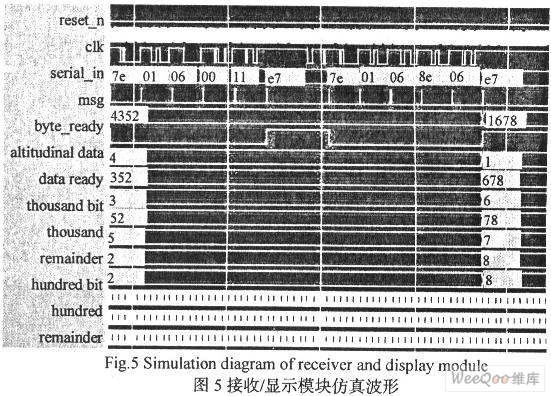
The simulation results of Figure 5 illustrate the functional characteristics of the data receiving/display module. The serial height data receiving module converts the serial data into parallel message data, and extracts the height data from the parallel message (1100h=4352, 068eh=1678), and does not restore the remainder of the stacked array divider to multi-bit binary coded The height data is converted into a thousand, one hundred, ten, one-bit BCD code and sent to the scanning seven-segment display controller. The scanout signal selects one of the four seven-segment common anode digital tubes, and the leddata corresponds to seven cathode pins respectively, corresponding to the segmentation string "abcdefg", so that one bit turns on and displays. Due to the visual memory, a stable multi-digit decimal height data display is seen. It can be seen from the simulation results that it is in complete agreement with the aforementioned design ideas.
4 Conclusion
The BIN code designed without the recovery of the residual array division to the BCD code converter requires only a small amount of shifting, adding/subtracting operations, etc. The algorithm has simple logic, regular structure and high speed, and is very suitable for occasions with high real-time requirements. And it is very easy to extend to other hex conversions. The pulse radar altimeter serial height data receiving/display module based on asynchronous serial data receiving, array division and dynamic display technology has been applied as a sub-module of an engineering in the design of a radar altimeter.
Edit: Nizi
35W UGR Downlights,Dimmable LED Downlight,UGR LED Downlight,Recessed LED Downlight
SHENZHEN KEHEI LIGHTING TECHNOLOGY CO.LTD , https://www.keheiled.com