Foreword
According to preliminary survey statistics, 75% of automobile traffic accidents are caused by the reversing of the car's "backsight" Xiaoliang. Therefore, many non-professional car drivers are eager to have a car reversing alarm. When reversing, constantly measure the distance between the tail of the car and the obstacle behind it, and display the distance at any time.
Different alarm signals are issued within the distance range to improve the umbrella of the car when reversing. Enhancing the rear view capability of the car, especially enhancing the rear view capability of large and heavy vehicles, is very important for improving driving safety and reducing the labor intensity and psychological pressure of the driver.
At present, both domestic and foreign are studying how to use advanced technology, namely car collision avoidance technology, to assist car drivers in real-time monitoring of people, vehicles and road environments that affect road traffic safety. In critical situations, the system actively interferes with driving and maneuvering. Assisting the driver to carry out emergency treatment and anti-Ib car
The occurrence of a collision accident. With the improvement of the requirements of the ease of use of the driver's assistance system, the small price drop of the single chip microcomputer and the networked development of the automotive electronic system, the new reversing radar is an intelligent ranging sensing system with the single chip as the core. This paper introduces an ultrasonic reversing radar monitoring and alarming system based on MSP430 single chip microcomputer.
1 system ranging principle
The ultrasonic transmitter emits ultrasonic waves in a certain direction, and starts timing at the same time as the transmission time. The ultrasonic waves propagate in the narrow air, and immediately return to the obstacle when the obstacle is encountered on the way, and the ultrasonic receiver stops the timing immediately upon receiving the reflected wave, and the ultrasonic wave is in the air. The speed of medium propagation is 340m/S. According to the time t, the distance S from the obstacle to the obstacle can be calculated.
S=340&TImes;t/2 (1)
This is the time difference ranging method. The system is to use the single-chip microcomputer to control the ultrasonic transmitter to emit the super Lubo pulse, and at the same time use the counter in the single-chip microcomputer to start timing. When the ultrasonic wave reaches the back obstacle, it will be reflected back. After receiving the echo signal, the receiving device generates a high level by the external comparison circuit to cause the external interrupt of the microcontroller. The MCU operation interrupt service subroutine (ISR) calculates the distance and transmits it to the LCD for display to the driver. At the same time, there is a comparison module in the program. If the distance is less than 5 m, the measured distance is displayed and the MCU outputs a high level. The buzzer is alarmed. If the distance is greater than 5m, U is displayed. U, the buzzer does not alarm, so that the driver can be reliably given alarm information in both sound and light ways to ensure the safety of reversing or driving.
2 system hardware design
2.1 main controller selection and hardware components
Compared with the commonly used 5 1 series MCUs, MSP430 series MCUs are powerful, low power consumption and high integration. The main disadvantage is that the price is slightly higher. In order to get the right price/performance ratio, we chose TI's early production of MSP430F101. This type of MCU is cheaper, although the function is not strong, but the foot 110 meets the requirements of this system. The disadvantage of F 1 is that there is no liquid crystal 162 drive, and the selection of a reasonable price liquid crystal display driver chip HT 1 can solve this problem.
The system hardware circuit is based on the MPS430F1101 single-chip microcomputer. It is mainly composed of ultrasonic transmitting circuit, ultrasonic receiving circuit, power supply circuit and alarm circuit.
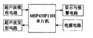
Picture 1 system hardware composition block diagram
2.2 Ultrasonic emission signal
The block diagram of the ultrasonic transmission hardware circuit is shown in Figure 2. The one-shot trigger receives the square wave of the 40ms trigger output from the P1.3 port output of the S430F1101 and the pulse width control output frequency is unchanged, and the high-level width is 160us. The square wave period is 40m s. This pulse signal acts as a set pulse for the 555 oscillator. During the set period, 555 periodically generates 40 oscillating signals, and the ultrasonic transmitting head T40K 1 converts the electrical signals into ultrasonic waves. The ultrasonic transmitter emits a pulse train with a pulse number of 7 (1/40 kHz=O.25 ms), and the sound wave of the ultrasonic transmitter is transmitted to the receiver by the reflector, and the propagation distance is 2 times the measurement distance. Formula (1) is known.
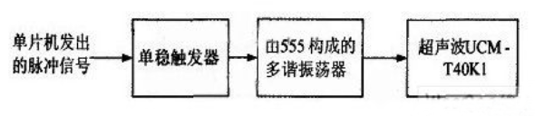
Figure 2 ultrasonic transmission hardware circuit
Tin Zinc Alloy Wire is a kind of electronic welding material speciallized for metal spraying of the end face of metalized film capacitor.The capacitors have been widely used in high-speed rail,automobiles,new energy and aerospace fields.
Application Fields: Metal spraying material is a kind of electronic welding material specialized for metal spraying of the end face of metalized film capacitor.
Tin Zinc Alloy Wire
Tin Zinc Alloy Wire,Zinc Alloy Wire,Tin Zinc Alloy Soldering Wire,Alloy Wire
Shaoxing Tianlong Tin Materials Co.,Ltd. , https://www.tianlongspray.com