IntroductionIn recent years, countless articles have focused on new display technologies. Typical topics have covered: the explosion of TFT color LCD panels with ever-increasing size into laptops and flat-screen monitors; PDP (plasma display panels) for high-definition TV CRT replacement; polymer LED (PLED) or organic LED (OLED) displays for the small color displays in games, cell phones, and PDAs.
This article discusses a 35-year-old display technology that itself has rapidly changed—the LED. This overview covers the origins of LEDs, their traditional applications, and how improvements in the technology have stimulated new applications.
A Brief History of LEDs Commercial research into LED technology started in 1962, notably at Bell Labs, Hewlett-Packard® (HP®), IBM®, Monsanto®, and RCA®. Work on gallium arsenide phosphide (GaAsP) led HP and Monsanto to introduce the first commercial 655nm red LEDs in 1968. In 1971 HP released the 5300A 500MHz portable frequency counter using a GaAsP LED display. LED displays flourished in the early 1970s as numeric displays in pocket calculators. For a short time, LEDs appeared in digital watches , but were soon replaced by LCDs. Meanwhile, LEDs replaced incandescent and neon lamps as status indicators, and became the standard numeric and alphanumeric display choice for instrumentation.
In the 1970s and 1980s the LED's hottest competition for consumer goods came from vacuum fluorescent displays (VFDs), whose bright blue-green display offered high intensity and high contrast when viewed through a green or blue filter. VFDs were first developed by ISE Electronic Corporation in 1967. ISE, often known by the division name of Noritake®, together with Futaba® and NEC®, offered display tubes from the late 1960s and early 1970s, starting with simple single-digit displays used in the rapidly growing desktop-calculator market . Multidigit display tubes appeared soon thereafter, reducing manufacturing cost. These tubes are possibly best remembered for their appearance in the popular Casio® pocket calculators. Later, Samsung ™ started making tubes for their own consumption for use in consumer goods. In 1993, NEC sold their complete manufacturing line to ZEC in China. Today NEC, Futaba, ISE, Samsung, and ZEC produce around 95% of the world's VFD tubes production.
In the 1980s and forward, monochrome LCDs competed strongly with LEDs and VFDs for consumer devices, instrumentation, and automotive panels. With the advantage of lowest power and easy customization, LCDs became the obvious choice for battery-operated applications. Although LCDs do not emit light, there are many applications where ambient light can be guaranteed. Alternatively, the light from a couple of green, orange, or yellow LEDs can be diffused and spread behind a small (10 square centimeter) LCD with an opaque plastic molding to provide an inexpensive and pleasant backlight.
Who Manufactures LEDs? The worldwide production of LEDs is now around 4 billion units a month. Ten years ago, Japan was the principal LED producer, and Taiwan's output was a little over 10% of the world's demand. According to the ITIS (Industrial Technology Information Service) of Taiwan, Taiwan now produces around half the world's demand from its more than 30 LED manufacturers; Japan and the USA are recorded as the next most productive LED manufacturers. Most LED manufacturers are actually assemblers and packagers, buying wafers or dice from foundries in Japan, the USA, and (more recently) Taiwan.
The CIE, Lumens and CandelasThis short digression on radiometric and photometric theory is useful background to the main discussion. Radiometry measures radiant energy at all wavelengths (visible and invisible). Photometry measures apparent brightness to the human eye. The human eye 'sees' the 380nm to 740nm range of light wavelengths as the familiar color spectrum (Figure 1).
Figure 1. Wavelength of color.
The Commission Internationale de l'Eclairage (CIE) formalized standards for the measurement of light and the response of the human eye, or 'standard observer,' in the 1930s. These standards characterized the variation in eye response over the entire visible range under a variety of lighting conditions, such as daylight and night. The CIE also defined the primary colors (Table 1). These standards and definitions have been controversial, and other standards exist.
Table 1. CIE Definition of Colors
| Color Name | Wavelength |
| Red | 700nm |
| Green | 546.1nm |
| Blue | 435.8nm |
When discussing LEDs and displays, it is important to note that the human eye response peaks roughly at green at 555nm, is sensitive to yellow, and falls off sharply toward blue at 400nm and toward red at 700nm. This can be seen in the 1931 photopic (daylight) chromaticity diagram, shown in a simplified form in Figure 2. The curve for scotopic (night-adapted) is quite different, peaking at about 512nm.
Figure 2. Human eye daylight color response.
Radiant light intensity (all wavelengths) is measured in lumens. The lumen definition states that 683 lumens of light is provided by 1 watt of monochromatic radiation at a wavelength of 555nm. Luminous intensity, in candelas (cd), results from the application of the CIE color response to the radiant flux, and provides the measurement for the visible portion of a light source. Display intensity, therefore, is described in cd or mcd to indicate the light output that is useful to the observer.
What are LEDs? A light-emitting diode (LED) is a PN junction semiconductor diode that emits photons when forward biased. The light-emitting effect is called injection electroluminescence, and it occurs when minority carriers recombine with carriers of the opposite type in a diode's bandgap. The emitted light's wavelength varies primarily from the semiconductor materials used, because the bandgap energy varies with the semiconductor. Not all injected minority carriers recombine in a radiated manner in even a perfect crystal; nonradiated recombination occurring at defects and dislocations in seemingly identical diodes can produce wide variations in useful emissions. This means, in practice, that manufactured batches of LEDs are sorted and graded for intensity matching.
LEDs are processed in wafer form similar to silicon-integrated circuits, and broken out into dice. Chip size for visible-signal LEDs generally fall in the range of 0.18mm square to 0.36mm square (Figure 3). InfraRed (IR) LEDs can be larger to handle peak powers, and high-power LEDs for lighting are yet larger.
Figure 3. Typical GaP LED die.
The simplest packaged LED product is the lamp, or indicator. The basic structure of an LED indicator consists of the die, a lead frame where the die is actually placed, and the encapsulation epoxy, which surrounds and protects the die and disperses the light ( Figure 4). The die is bonded with conductive epoxy into a recess in one half of the lead frame, called the anvil due to its shape. The recess in the anvil is shaped to project the radiated light forward. The die's top contact is wire bonded to the other lead frame terminal, the post.
Figure 4. Typical LED indicator and cutaway showing construction.
The mechanical construction of the LED lamp determines the dispersion or radiated light pattern. A narrow radiated pattern (Figure 5) will appear very bright when viewed on-axis, but the viewing angle will not be very wide. The same LED die could be mounted to give a wider viewing angle, but the on-axis intensity will be reduced. This tradeoff is inherent in all LED indicators, and can be easily ignored. High-brightness LEDs with a 15 ° to 30 ° viewing angle are a good choice for an information panel directly in front of an operator; a wide-direction indicator or automotive dashboard might require an angle as wide as 120 °.
Figure 5. Narrow LED indicator radiation pattern.
LED Numeric and Alphanumeric Display ConstructionThe familiar 7-segment numeric display digit actually suffers from a misnomer, as there is nearly always an 8th segment for the decimal point (DP). The less familiar 'starburst' alphanumeric displays are similarly referred to as 14- segment and 16-segment digits, again, ignoring the DP. Starburst displays provide an economical way of showing the full 26-character Roman alphabet in upper case, as well as the numerals 0 to 9. The difference between the 14-segment and the 16-segment digit types is that the top and bottom bar is split on the 16-segment digit, improving the appearance of some characters (Figure 6).
Figure 6. 7-segment, 14-segment, 16-segment, and 5 x 7 matrix digit types.
The 5 x 7 matrix is ​​even more versatile, capable of displaying the Roman alphabet in both upper and lower case and a wide variety of symbols. The difference in the display quality is shown in Figure 7, which compares the characters displayed using the 5 x 7 matrix font map of the Maxim MAX6952 / MAX6953 display driver with the characters displayed using the identical font map of the Maxim MAX6954 / MAX6955 starburst display driver. The 5 x 7 matrix is ​​inadequate for CJK (Chinese-Japanese-Korean) characters, and a font granularity of 12 x 12 is often cited as a minimum resolution.
Figure 7. Comparing 5 x 7 matrix and starburst characters.
Most LED numeric and alphanumeric display digits are actually hybrids, mounting multiple LED chips in a package. Some very small display digits (for example the "bubble-top" calculator displays popular in the 1970s) are monolithic. Whether a numeric and alphanumeric display, the shape of each segment is defined by a reflector and light-pipe mounted around the LED die, not by the die itself. Small displays use one die per display segment, while large displays may use two or more dice per segment to spread the light effectively and show reasonably uniform intensity across the segment.
In the manufacturing process, the chips are mounted on either a lead frame or a PCB and wire bonded to an interconnection pattern. The dice are mounted using conductive paste, because the die substrate forms one of the two diode connections (Figure 8). The interconnection pattern usually connects either the anode- or the cathode-LED chip connections together to reduce the number of pins required for the digit. As a result, displays are referred to as CA (common anode) or CC (common cathode) types, and integrated circuit display drivers will specify one type or the other (Figure 9).
Figure 8. Mounting an LED die to form a digit segment.
Figure 9. Common-anode and common-cathode LED digit types.
The lead-frame method of construction is similar to that used for integrated circuit manufacturing. The frame is normally etched silver-plated steel, providing good heat conduction and light reflection. The reflector channel forming the light pipe for each segment is epoxy-filled during construction, and the epoxy provides the mechanical strength and the environmental protection to the display.
A less costly construction method uses a PCB-type substrate instead of a lead frame. Displays built this way are often referred to as 'stick' types, because the method is commonly used to build multidigit displays, for example 4-digit clock LEDs. Stick construction allows the display to be built without epoxy fill, which saves cost but leaves the display susceptible to degradation from contaminants.
LED Electrical and Optical Characteristics The electrical behavior of LEDs is similar to other semiconductor diodes. The forward voltage is higher, and differs for the various materials used for different colors (Figure 10). The forward voltage rises with current and falls with temperature by about 2mV / ° C. Like all semiconductors, moreover, the LED must be derated at higher operating temperatures.
Figure 10. LED forward voltage varies with color and current.
The optical behavior of the LED varies significantly with temperature. First, the amount of light emitted by the LED lamp falls as junction temperature rises. This is because of an increase in the recombination of holes and electrons that contribute nothing to light emission. Also, the emitted wavelength changes with temperature, mainly because the semiconductor's energy gap changes with temperature.
Driving LEDs—Static Drive and Multiplex DriveThe easiest way to drive multiple LEDs, such as display digit segments, is to drive each LED separately with a resistor or current source setting the forward current. This technique is called static drive because the LED current is continuous . Static drive is useful when relatively few LEDs are driven, with the sensible limit about two 7-segment digits. High-efficiency LEDs can be driven to high brightness with 2mA, which is available from the output ports of most microcontrollers.
When driving more segments, static drive demands an larger number of drive outputs, 1 per LED. Multiplex, or pulse drive reduces the drive connections by strobing only a small number of segments (typically a complete digit) at a time. The strobing is done at a high enough repetition rate that the eye perceives continuous illumination. However, the LEDs require a higher current to compensate for the reduced duty cycle.
An advantage of pulse drive is that the human eye behaves as a partially integrating and partially peak-reading photometer. As a result, the eye perceives rapidly pulsed light somewhere between the peak and the average brightness. This means that a low-duty-cycle , high-intensity pulse of light looks brighter than a DC signal equal to the average of the pulsed signal. An advantage of multiplexed operation, therefore, is an improvement in display intensity for a given average power consumption.
The efficiency of an LED typically rises with forward current, presuming constant junction temperature. However, this is not always the case. LED data sheets should be carefully examined (and compared) when choosing the optimum peak current (Figure 11). Multiplying can often provide 1.5 times the light output from the average drive current of the cycle, compared to the equivalent DC level.
Figure 11. LED light output vs. current.
As LED drive currents increase for multiplexing, internal temperatures within the LED also increase. There is a point at which the temperature increase causes a drop in photon conversion efficiency, which, in turn, negates the effect of the increased current density through the junction. At this point, increasing drive currents can result in a small increase, no change, or even decrease in light outputs from the LED chip.
The standard connection for multiplexing LED digits uses a separate pin for each digit's common-cathode connection, while the anodes are tied together across all the digits (Figure 12). The number of connections required is one for every digit used, plus one for every segment within a digit. A more pin-efficient scheme relies on the fact that during the multiplex operation, only one digit-drive output is actually in use. By making the LED drive pins alternate duty between driving digits and segments, n drive pins can be used to drive n digits each with n-1 segments. The Maxim MAX6951 LED driver uses this technique to drive eight numeric digits with only nine pins (Figure 13).
For Larger Image
Figure 12. Standard connections for multiplexing.
For Larger Image
Figure 13. Reduced pin-count multiplexing, MAX6951 connections.
LED Life ExpectancyLEDs have a MTBF (mean time between failures) usually in the range of 100,000 to over 1,000,000 hours. This is a long time for continuous operation, considering that a year is 8760 or 8784 hours. In practice, the useful measure of LED lifetime is its half-life; an LED is deemed to have reached the end of its life when the light output falls off to half the original.
When current flows through an LED junction the current flow is not uniform, resulting in small temperature differentials within the chip. These temperature differentials exert stress on the lattice, causing minute cracks to occur. These lattice defects accumulate with use, and reduce the photon conversion efficiency of the chip, thus reducing light output. The attrition rate varies from the LED material, temperature, humidity, and the forward current.
Blue and White LEDs There are essentially two technologies for generating white light from LEDs. One way is to mount a red, a green, and a blue die very close together within a package, and mix the light outputs in the correct proportions to achieve what the the human eye perceives as white light. Ignoring the technical issues of setting the correct LED drive levels, the problem with this approach, is the cost of three dice. Nonetheless, tricolor LEDs are popular for LCD backlights in consumer applications because the user can set the backlight color to any hue desired.
The most cost-effective approach, pioneered notably by Nichia®, includes a phosphor with the blue LED that absorbs some of the blue light and fluoresces in a second color to achieve a near-white light. Some early white LEDs using this technique showed a noticeable blue tinge, but the most recent developments are excellent and can be seen in full-color PDAs and cell phones.
As recent as 2000, white LEDs typically had a forward voltage drop of 4V to 4.2V. This required cell phone designers to include a step-up DC-DC regulator to increase the Li + battery voltage (3.6V typically) to drive the LEDs. White LEDs are now being produced with only a 3V to 3.1V forward voltage drop. This allows cell phone designers to drive the LEDs directly from the battery for backlighting.
Recent Applications for LEDsLED processes changed rapidly in the 1980s with the emergence of high-efficiency GaAlAs and ultra-efficient InGaAlP LEDs (Table 2). The quantum efficiency of LEDs greatly increased. All primary colors (RGB) became available, with reliability as good or better than the other display technologies. Surface-mount LEDs are now available in single-color (including white), bicolor (usually red and green), and tri-color formats (Figure 15). These highly efficient and ultra-bright LEDs are being designed in backlights for LCD panels, equipment panels, and indoor message boards. LEDs are also being designed as the light source for the flash on cell-phone cameras.
LEDs are increasingly designed into outdoor message boards, instead of filtered incandescent lamps, by grouping the LEDs close enough so that the light outputs merge to create a typically 25mm square pixel (Figure 14). These message boards, or variable message signs, are used for advertising displays and traffic signs. Companies such as Daktronics? are incorporating LEDs into stadium displays and advertising signs. In addition, LEDs are being designed into marquees / scrolling message signs, gaming machine 'toppers,' and gaming-casino progressive display signs.
Another rapidly growing market is traffic lamp replacement. Incandescent traffic lamps draw between 75W and 150W, depending on size (20cm or 30cm) and color (due to differences in the transmissivity of the red, green, and orange filters used). LED traffic lamps draw around 7W to 15W, and can be replaced every five years instead of every six months for incandescent lamps. LED traffic lamps will save cities money, time, and the manpower required to close lanes of traffic to replace an incandescent.
Table 2. LED Processes
| Light Emitting Layer | Timeline | Comments |
| GaAsP (Gallium arsenide phosphide) | 1960s | Original low efficiency red using liquid phase epitaxy |
| GaP (Gallium phosphide) | 1970s | High efficiency red |
| GaA | As (Gallium aluminum arsenide) | 1980s | Single and double heterostructure processed using vapor phase epitaxy increase efficiency |
| InGaA | P (Indium gallium aluminum phosphide) | 1990s | Metal organic vapor phase epitaxy |
| InGaN (Indium gallium nitride) | 2000s | Ultrabright green and blue |
Figure 14. LED cluster pixel for outdoor message boards.
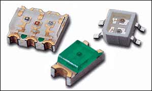
Figure 15. Surface mount LEDs from Everlight â„¢.
Future Applications for LEDsCurrent ultra-bright LEDs exceed the light output of incandescent and halogen lamps and are not subject to the maintenance requirements (a life of a few thousand hours at best) associated with filament lamps. The 100-watt incandescents typically produce 15 to 20 lumens / watt. Ultra-bright white LEDs are now producing 20 to 60 lumens / watt. Companies such as Nichia and Lumileds are designing ultra-bright LEDs capable of more uniform lighting in styles such as warm white, cool white, and commercial white . There are numerous applications for these LEDs: fluorescent light replacement, home lighting, automotive headlight and dome lighting, television backlighting and flashlights, to name a few.
Standard fluorescent lights typically produce 80 lumens / watt. As these ultra-bright LEDs near that output level, they figure to replace fluorescent bulbs in offices around the world at some point in the future. These ultra-bright LEDs pollute less and have a much longer lifetime than fluorescents.
LEDs are easily dimmed using PWM and other techniques. The goal of the LED process developers is to build a very-high-brightness white LED economical enough for domestic lighting. There is interest in high-efficiency, long-life lamps by hotels and factories because of the electricity cost and the labor cost to replace the bulbs.
Organic LEDs (OLEDs) will probably be designed into more applications: cell phones, big-screen televisions, notebook monitors, car navigation systems, and billboards. OLEDs produce brighter images, allowing customers to see their cell phone or notebook screen in direct sunlight. High brightness is achieved at low drive voltages and current densities.
Comparison of Display Technologies For a comparison of display technologies, please refer to Application Note 1193 :, Electronic Displays Comparison.
A similar version of this article appeared in the October 2002 issue of Elektronik Industrie magazine.
Casio is a registered trademark of Casio Computer Company Inc.
Futaba is a registered trademark of Futaba Denshi Kogyo Kabushiki Kaisha Corporation of Japan.
HP is a registered trademark of Hewlett-Packard Development Company, LP
IBM is a registered trademark of International Business Machines Corporation.
Itron is a registered trademark of Noritake Itron Corporation.
NEC is a registered trademark of NEC Corp.
Nichia is a registered trademark of Nichia Corporation.
LED DJ Booth is used different product models and structures as different conditions, which can be customized to the scene modeling. It can be spliced out the unique shape with different sizes of triangles, rectangles, hexagon. Unique DJ Table is not limited to kinds of environment. The application of the relevance and the shape of DJ LED Video Wall can enhance scene recognition.
LED Bar Display will not only present a delicate and realistic color performance through the synchronization adjustment, but also is compatible with different sources of input such as TVV, HDV, DVI, VGA, SDI. We adopt SMD technology to achieve super-wide viewing angle and better surface smoothness. Super light cabinet is to realize easy installation and maintenance that can be customized for shapes, sizes, pixels, resolution.
LED DJ Display, LED DJ Booth, DJ LED Video Wall, LED Bar Display
Shenzhen Priva Tech Co., Ltd. , https://www.privaled.com