IntroducTIonThe MAX9205 / 9207 serializers and MAX9206 / 9208 deserializers are designed to transmit high-speed data over a point-to-point interconnection. The serial "payload" data rate is 400Mbps to 600Mbps for the MAX9207-MAX9208 and is 160Mbps to 400Mbps for the MAX9205-MAX9206. Both pairs have the same configuration and differ only in operating frequency. In this app note we will focus on the higher data rate MAX9207 serializer.
The serializer and deserializer can be used in applications needing fast data interconnections such as telecom / network backplane data exchanges, 3G cell phone basestation interconnection, and video display panel interfaces. The advantages of LVDS interconnection are simple configuration, low transmission power, low cost cable , high data rate, long reach, and low EMI. The LVDS standards (ANSI TIA / EIA-644 and IEEE 1596.3) specify the signal level, waveform, and timing, but not the cable type, data rate, bus structure, and link distance. They offer users the flexibility to apply LVDS signaling to various applications but require familiarity with the characteristics of LVDS on the data rate, bit error rate (BER), cable length, and cable type. This application note presents laboratory test results and analysis of the quality of LVDS signaling under different data rates and cable lengths. It is expected that this note will provide system designers with some guidance in their applications.
Signal quality is quantified by measuring the jitter and amplitude of LVDS eye diagrams at various date rates and cable lengths. The eye diagram is used because it requires simple equipment and is easy to conduct compared to a BER test. A BER test requires a long test time. For instance, a BER test to verify an error rate of 10-12 needs at least 1014 bits. At 400Mbps, almost 3 days would be required to send and receive 1014 bits. To verify a BER of 10-13 would take a month. The jitter of an eye diagram is directly linked to the signal quality from which we can predict the reliability of the data link. Measurement Setup In the conducted tests, the LVDS signal is transmitted from the MAX9207 LVDS serializer. The MAX9207 latches 10-bits of parallel input data, adds two overhead synchronization bits and transmits the serialized data stream through a single LVDS output. The parallel data clock (TCLK) can be as high as 60MHz. With the two synchronization bits included, the serial rate (called "link data rate" in the tables) is 12 x TCLK. The "payload" data rate (the transfer rate of the parallel data) is 10 x TCLK. The functional block of MAX9207 is shown in Figure 1.
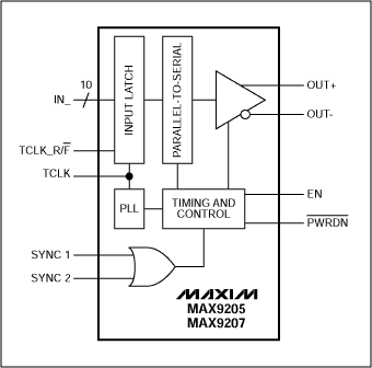
Figure 1. Function block diagram of the MAX9207.
The test setup is shown in Figure 2. The 10-bit parallel data is generated by the Sony / Tektronix DG2020A digital signal generator. A repeating 512 random bit sequence is output to each bit of the MAX9207 parallel input. Each random sequence is generated by a 32-bit shift register with randomly selected coefficients. Each output has a different set of coefficients. The cable is unshielded Ethernet Category 5, AWG 24, twisted-pair. We tested various cable lengths: 5ft, 15ft, 30ft, and 60ft. One end of the cable is connected to the MAX9207 output using two through-holes (1A and 1B) on the MAX9207 EV board. The other end of the cable is terminated by a 100Ω resister. The eye diagram is measured on a Tektronix TDS784C oscilloscope using a Tektronix P6247 1.0GHz differential probe. The oscilloscope is synchronized with the MAX9207 parallel rate clock.
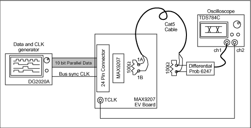
Figure 2. Eye diagram measurement setup. Test Results Four groups of tests are conducted. In each group, a different cable length is selected and the link data rate is varied from 480Mbps to 720Mbps. This link data rate includes the two synchronization bits, making the "payload" data rate from the 10-bit parallel input 400Mbps to 600Mbps. The total jitter tTJ is measured at the line of zero differential voltage and the quantity tUI is the duration of a bit symbol (see Figure 3). In addition to measuring tTJ, we also measure another jitter called marginal jitter tMJ related with differential voltage of the LVDS signal (see Figure 3). As shown in Figure 3, the jitter tMJ is measured from the center of the zero-crossing of eye-diagram to the point where the peak-to-peak differential voltage is equal to 300mV. With the marginal jitter tMJ, we can measure the margin for the data rate that can be reliably recovered by the deserializer MAX9208. The differential peak-to-peak voltage is defined as VP-P. VP-P is two times the magnitude of the difference of the single-ended voltages at the measurement point, or VP-P = 2 × | (VOUT +)-(VOUT-) |. For example, at the measurement point, if VOUT + = 1.35V and VOUT- = 1.10V relative to ground in the high state and VOUT + = 1.10V and VOUT- = 1.35V relative to ground in the low state, then VP-P = 500mV. Since the measurements are made with a differential probe (which subtracts VOUT- from VOUT +) the eye diagrams show VP-P. Intuitively, tUI-tTJ is a measure of eye diagram width and VP-P is the amplitude.
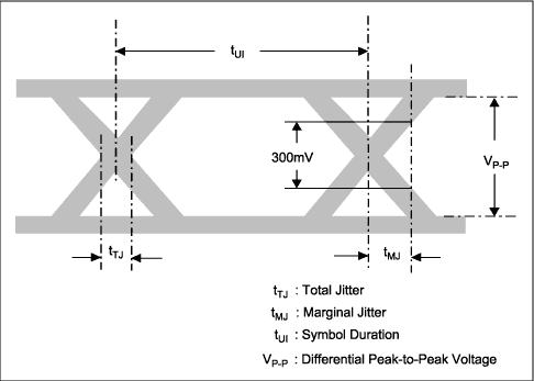
Figure 3. Jitter measurement at zero differential voltage line.
Table 1 records the measurements of the tests of the four groups with cable lengths from 5ft to 60ft. In the table, the link data rate is the actual rate on the LVDS link.
Table 1. Total Jitter tTJ and Peak-to-Peak Differential Voltage VP-P of Eye Diagram
| Link Data Rate (Mbps) | Symbol Duration tUI (ps) | Total Jitter tTJ (ps) * | Marginal Jitter tMJ (ps) * | Differential Voltage VP-P (mV) * | |
| 5 feet | 480 | 2083 | 100 | 130 | 936 |
| 540 | 1852 | 100 | 150 | 920 | |
| 600 | 1667 | 100 | 160 | 912 | |
| 660 | 1515 | 110 | 160 | 904 | |
| 720 | 1389 | 110 | 160 | 895 | |
| 15 feet | 480 | 2083 | 130 | 200 | 808 |
| 540 | 1852 | 130 | 200 | 788 | |
| 600 | 1667 | 130 | 210 | 768 | |
| 660 | 1515 | 140 | 210 | 736 | |
| 720 | 1389 | 140 | 220 | 704 | |
| 30 feet | 480 | 2083 | 230 | 320 | 564 |
| 540 | 1852 | 230 | 360 | 556 | |
| 600 | 1667 | 230 | 360 | 530 | |
| 660 | 1515 | 240 | 370 | 492 | |
| 720 | 1389 | 240 | 380 | 450 | |
| 60 feet | 480 | 2083 | 300 | 540 | 436 |
| 540 | 1852 | 300 | 560 | 412 | |
| 600 | 1667 | 320 | 580 | 384 | |
| 660 | 1515 | 340 | 600 | 348 | |
| 720 | 1389 | 360 | 640 | 338 |
In Figures 4, 5 and 6, we plot the jitters and differential voltage versus the link data rate.
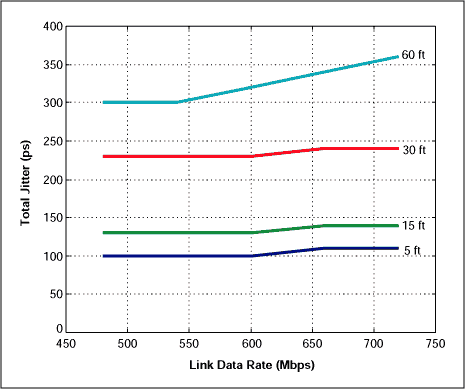
Figure 4. Total jitter tTJ vs. link data rate.
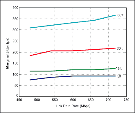
Figure 5. Marginal jitter tMJ vs. link data rate.
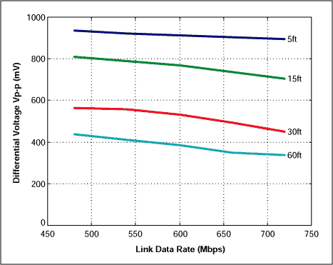
Figure 6. Differential voltage VP-P vs. link data rate.
From the measurements, we can observe a few facts. From 5ft to 30ft, tTJ and tMJ increase slowly vs. the link data rate. As the cable length increases to 60ft, the jitter increases rapidly with the link data rate. For jitter vs. cable length, both increase slowly below 15ft, and then much faster for 30ft and 60ft. For differential voltage vs. link data rate, VP-P changes almost linearly in terms of the link data rate. There is a big increment as the cable length goes from 15ft to 30ft. Overall, it shows that the LVDS signaling provided by the MAX9207 can have a long reach on low cost CAT-5 unshielded twisted cable.
The MAX9208 deserializer is designed to receive the serialized data sent from the MAX9207. According to the data sheet of MAX9208, it can recover data reliably with the marginal jitter tMJ less than 720ps at 480Mbps and 320ps at 720Mbps. With a linear interpolation we get the upper limits of the marginal jitter for the rates between 480Mbps and 720Mbps (see Table 2). These upper limits provide us the criteria for determining the reliable transmission rates for various cable lengths. To provide a conservative result, we tighten the jitter upper limits by 10%. Table 3 shows the data rates the MAX9207 can transmit and the MAX9208 can recover reliably under different cable lengths in terms of the tightened jitter upper limits. Figure 7 plots these results in log scales.
Table 2. Upper Limits of the Marginal Jitter for Different Link Data Rates
| Link Data Rate (Mbps) | Symbol Duration tUI (ps) | Upper Limits of Marginal Jitter tMJ (ps) | 10% Tightened Upper Limits of Marginal Jitter tMJ (ps) |
| 480 | 2083 | 720 | 648 |
| 540 | 1852 | 620 | 558 |
| 600 | 1667 | 520 | 468 |
| 660 | 1515 | 420 | 378 |
| 720 | 1389 | 320 | 288 |
Table 3. Maximum Link Data Rates under Tightened Upper Jitter Limits of Different Cable Lengths
| Cable Length | Link Data Rate (Mbps) | Measure Marginal Jitter tMJ (ps) | 10% Tightened Upper Limits of Marginal Jitter tMJ (ps) |
| 5ft | 720 | 160 | 288 |
| 15ft | 720 | 220 | 288 |
| 30ft | 660 | 360 | 378 |
| 60ft | 528 | 570 | 576 |
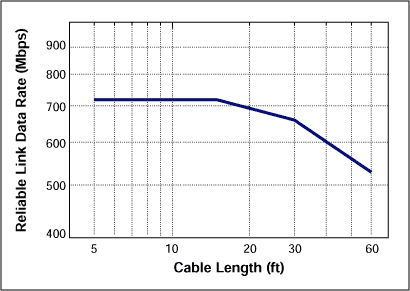
Figure 7. Reliable link data rates for different cable lengths.
The above results show that for 5ft and 15ft cables, the data rates are bounded by the highest operation data rate (720Mbps) of the MAX9207 serializer. As the cable length goes beyond 30ft, the data rate decreases as the length increases. Through these measurements , it demonstrates that the MAX9207 / 9208 serializer / deserializer pair can establish a reliable point-to-point high-speed data link with a single pair of CAT-5 cable for various applications. Figure 7 provides simple design guidance for users to select the cable length. To show some measured signals by the digital scope, Figure 8 presents the eye diagrams measured under the conditions in Table 3.
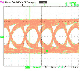 | 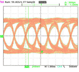 |
| 60ft, 528Mbps, tMJ = 560ps | 30ft, 660Mbps, tMJ = 360ps |
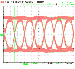 | 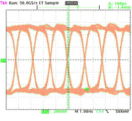 |
| 15ft, 720Mbps, tMJ = 220ps | 5ft, 720Mbps, tMJ = 160ps |
Figure 8. Eye diagrams of different cable lengths.
Since in some applications, it is preferred to use AC coupling between the serializer and deserializer by inserting two capacitors at the LVDS output pins. To demonstrate the effect of AC coupling, we inserted a 0.012µF ceramic chip capacitor in series with each serializer output. Figure 9 shows the eye diagrams for DC and AC coupling of 15ft cable at the data rate of 720Mbps. Comparing the eye diagrams of the two cases, we see that AC coupling reduces the differential voltage and increases the jitter slightly. We can ignore the effect of AC coupling on the signal integrity as long as the signal has a good zero DC balance.
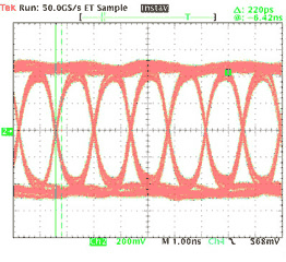 | 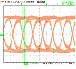 |
| 15ft, 720Mbps, DC coupling, tMJ = 220ps | 15ft, 720Mbps, AC coupling, tMJ = 240ps |
SC Fast Connector is a revolutionary field installable optical Fiber Connector that requires no epoxy and no polishing. The unique design of Fast Connector SC incorporates a factory-mounted fiber stub and a pre-polished ceramic ferrule. During the installation, SC fast connector does not require any adhesive and curing process. Installation of fast connector SC requires some fiber preparation tools,such as a fiber stripping tool, wipes and a fiber cleaver. No electrical power supply is needed for SC fast connector. SC Apc Fast Connector is already a popular solution for optical wiring inside buildings and floors for LAN & CCTV applications. Foclink,a reliable supplier of SC fast connector is always beside u 7*24.
SC Fast Connector
SC Fast Connector,SC Apc Fast Connector,Fast Connector SC
Foclink Co., Ltd , https://www.scfiberpigtail.com