Voltage transformers play a crucial role in power systems, serving as essential devices for voltage measurement and protection. They are mainly divided into two types: electromagnetic and capacitive voltage transformers. The primary winding of a voltage Transformer is connected to the high-voltage side of the system, while the secondary winding typically provides a standard output voltage of 100V. This low-voltage signal is then used by meters, relays, or other protective devices to monitor and control the electrical system safely.
One of the key advantages of using a voltage transformer is that it allows the measurement circuit to be electrically isolated from the high-voltage circuit. This isolation ensures the safety of both personnel and equipment, preventing dangerous voltage levels from reaching measuring instruments or control systems.
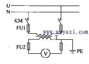
A basic voltage transformer circuit consists of a primary coil and a secondary coil wound around a common magnetic core. The primary coil is connected to the high-voltage source, and the secondary coil induces a proportional voltage based on the turns ratio between the two coils. This makes it possible to accurately measure high voltages without direct exposure to them.
The diagram below illustrates a typical voltage transformer setup, showing how the primary and secondary windings are arranged and how the output voltage is derived.
Output Transformer,Output Transformers,Pin Plug Switching Power Transformer,Output Switching Power Transformer
Huizhou Show-Grand Electronics Co., Ltd. , https://www.sgtransformer.com