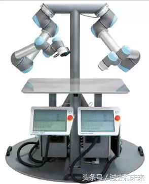
In recent years, major industrial robot manufacturers are currently keen to collaborate with human-machines, ABB's "corn", FANUC's "green arm", KUKA's "Eva", etc., before the comparison of human-computer collaboration The number is UR, let's briefly introduce the black technology of UR, and see how to teach robots by hand.
The UR5 robot has a very light weight (only 18.4 kg) and can be easily moved at the production site, and can be quickly integrated into the production line without cumbersome installation and setup, and interacts with employees. The programming process can be implemented in the teaching programming mode. The user can hold the UR arm, manually guide the arm, and run the arm once in the desired path and movement mode. The UR robot can automatically remember the movement path and mode. The robot operates through a unique, user-friendly graphical user interface with a wide range of features on the touch screen for the user to choose from. Any repetitive production process can use it and benefit from it.
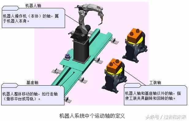
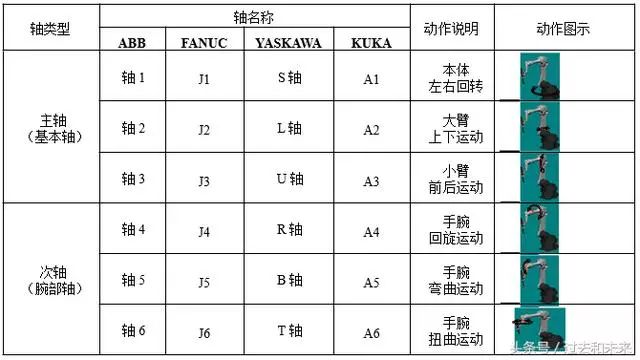
1, the name of the robot motion axis
Generally, the robot motion axis can be divided into a robot axis, a base axis and a tooling axis according to its functions, and the base axis and the tooling axis are collectively referred to as an external axis.
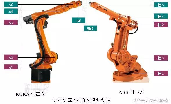
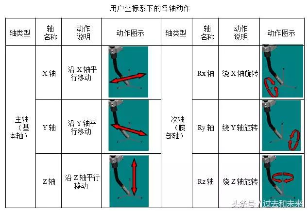
The A1, A2, and A3 three axes (Axis 1, Axis 2, and Axis 3) are called basic axes or spindles to ensure that the end effector reaches any position in the workspace. The A4, A5, and A6 three axes (Axis 4, Axis 5, and Axis 6) are called wrist or secondary axes and are used to return any spatial pose that implements the end effector.
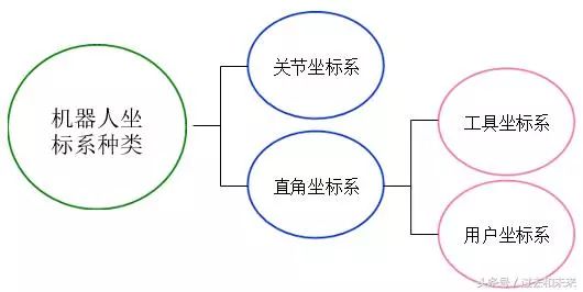
2. Types of robot coordinate systems
At present, in most commercial industrial robot systems, the joint coordinate system, the Cartesian coordinate system, the tool coordinate system and the user coordinate system can be used, and the tool coordinate system and the user coordinate system belong to the Cartesian coordinate system category.
TCP is the robot system control point. The factory defaults to the return center of the last motion axis or mounting flange. The TCP point will change after the tool is installed.
(1) Joint coordinate system
In the joint coordinate system, individual axes can be moved in either forward or reverse direction. For a wide range of motions, and without requiring a TCP pose, the joint coordinate system can be selected.
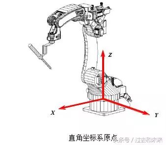
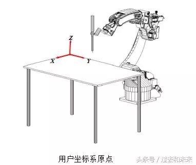
(2) Cartesian coordinate system (world coordinate system, geodetic coordinate system)
One of the coordinate systems often used in robot teaching and programming. The origin is defined at the intersection of the robot mounting surface and the first rotating shaft. The X axis is in front, the Z axis is in the Y axis, and the Y axis is determined by the right hand rule.
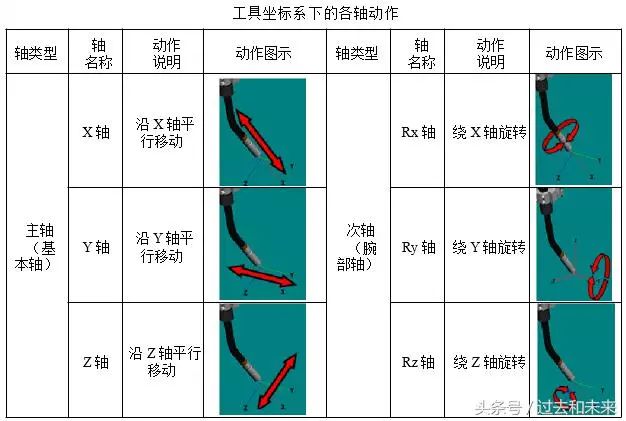
(3) Tool coordinate system
The origin is defined at the TCP point, and the effective direction of the tool is assumed to be the X-axis (some robot manufacturers define the effective direction of the tool as the Z-axis), while the Y-axis and Z-axis are determined by the right-hand rule. It is most appropriate to select this coordinate system when performing a translation operation that does not change the attitude of the tool relative to the workpiece.

(4) User coordinate system
The user coordinate system can be defined as needed. When the robot is equipped with multiple work stations, selecting the user coordinate system makes the operation easier. In the user coordinate system, the TCP point moves in the direction of the user-defined axis.
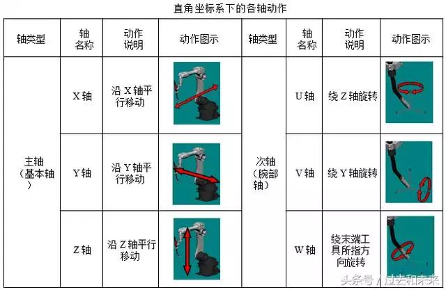
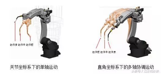
The functions of different robot coordinate systems are equivalent, that is, the actions performed by the robot in the joint coordinate system can also be realized in a Cartesian coordinate system.
The action of the robot in the joint coordinate system is uniaxial motion, while in the Cartesian coordinate system it is multi-axis linkage. In addition to the joint coordinate system, other coordinate systems can implement the control point invariant action (only changing the tool pose without changing the TCP position). It is often used in robot TCP calibration.
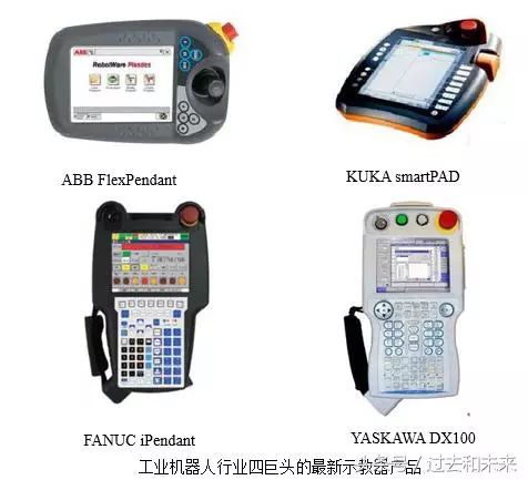
3. Know the teaching device
A color filter is an Optical Filter that expresses colors. It can precisely select the small range of light waves to be passed, while reflecting off other undesired wavelengths. The color filter is usually installed in front of the light source, so that the human eye can receive the saturated light of a certain color. There are infrared filters, green, blue, etc. Compared with UV filters and VD filters, it is a general term for colored filters. Such as contrast filter, color separation filter, LB filter, etc.
Colored glass exhibits different colors due to its absorption in the visible light waveband. Colored glass is widely used in laser protection, industrial measurement and environmental measurement instruments.
Black Glass Filter,Red Glass Filter,Yellow Glass Filter,Green Glass Filter
Bohr Optics Co.,Ltd , https://www.bohr-optics.com