There are a lot of information about the first-order filters, such as the cutoff frequency, phase shift, and so on, which are not repeated here. This article mainly describes the places where dumbs have been troubled during the learning process, and my brief analysis.
This article starts from the passive RC low-pass filter, with an example as the background: there is an ECG amplifier circuit, the final output impedance is 50 ohms, but the output signal of the circuit has obvious glitch, then we want to pass the low pass How does the filter filter out high frequency noise?
The easiest way to do this is to add a passive RC filter directly to the output. The frequency range of the ECG signal is: 0.05-100 Hz. To ensure that the useful signal does not produce too unbalanced attenuation in the passband, we design a cutoff. Low-pass filter with a frequency of 150Hz (because the signal has already produced 3dB attenuation when the cutoff frequency is reached, the generally selected cutoff frequency value is slightly larger than the highest frequency of the actual useful signal)
As shown in Figure 1:
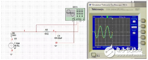
figure 1
The output amplitude has changed! The signal source outputs a peak 1V signal. When the filter is output, it can be seen from Figure 1, which is less than 1V (500mV per cell, less than two cells). what happened?
Separate the filter, inject the signal with an ideal voltage source, and observe the filter output:
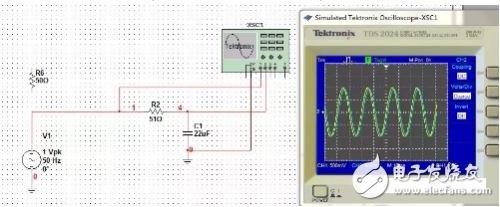
figure 2
At this point, the filter output basically reaches the peak 1V output. Plus the front-end circuit with output impedance can't be achieved, what is the reason? I always thought that the RC filter calculated the cutoff frequency according to the formula, and then selected the parameters, added to the circuit to OVER, it seems not so simple, it will be affected by the impedance of the front and rear stages, then how to determine the quantitative relationship? If you don't figure this out, the circuit design is like a dumb, staying in the primary stage of socialism.
Later we will explore the matching problem of the RC filter in the circuit:
Taking the above application as an example, suppose the output impedance of the pre-stage circuit is Ro1, the peak value of the output signal voltage is ±2V, and the input impedance of the latter stage circuit is RL2. Then, after adding the first-order passive RC low-pass filter, the latter stage What is the peak value of the actual received signal of the circuit?
The equivalent circuit of this example is as follows:
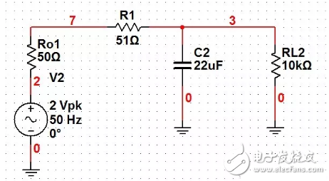
image 3
In the circuit design or analysis, regardless of the front and rear stages and their own input and output impedance, it is taken for granted that the peak value of the signal received by the latter stage is ±2V. Is there any wood? There is indeed a dumb, and because the measured output does not reach ± ​​2V, the anger is not given to the component parameters, and the circuit board design is not strong.
So how do you analyze it? First, let's look at the quantitative relationship of the pre-stage output to the RC filter:
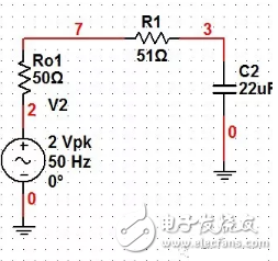
Figure 4
The signal source output impedance is Ro1 ohm, RC filter input impedance:
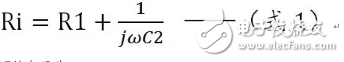
Then the voltage at Point7 in the figure is:

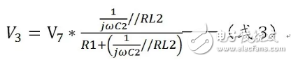
Then we look at the quantitative relationship of the RC filter to the input of the latter stage:

Figure 5
Point 3 voltage in the figure:
It can be seen that for the first-order RC filter, after inputting the circuit, the input and output impedances of the front and rear stages will affect the characteristics of the circuit, and the output characteristics of the RC filter circuit are not constant.
Another point to note is that in Figure 4 above, we assume that the input impedance of the latter stage is infinite; in Figure 5, the output impedance of the front stage is zero. So, how is the quantitative relationship calculated for the circuit of Figure 3?
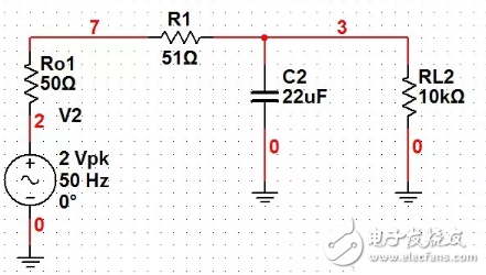
Figure 6
For the convenience of calculation, we take Figure 3 above, that is, Figure 6:
For the analysis, we get the formula 1 when we ask for Point 7, but after accessing RL2, Ri is affected by RL2:
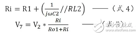
From the above formula:

It can be seen that for the first-order passive RC low-pass filter, the impedance matching or not has a great influence on the output of the filter. The selection of the parameters of the filter is very important.
Still in the above filter with a cutoff frequency of 150 Hz, for the parameter selection of R1 and C2, it can be:

Table 1
It can be seen that for the same cutoff frequency, the parameters can also select different values, and the different values ​​have different performances in the circuit. For the matching with the superior input, it is desirable that the larger the R1+Xc, the better. For the matching with the latter level, it is hoped that Xc is much smaller than RL2, which leads to an optimization problem. When designing the circuit, it is not only necessary to set the cutoff frequency to the reasonable value of R1 and C2, but also to consider the input and output impedance of the front and rear stages. Let us look at two extreme cases:

Figure 7

Figure 8
In Figure 7, the output impedance of the front stage is large, and the input impedance of the latter stage is small. (This situation is obscenity to discuss the impedance matching problem for the RC network. As for the actual situation, it will not happen, huh, huh~~) . The parameters selected by the RC network make the input impedance smaller and the output smaller.
In Figure 8, the output impedance of the front stage is ideal, and the input impedance of the latter stage is large.
Comparing the voltage amplitudes of Point2, Point7 and Point3 in the two graphs, we can find that the output gray in Figure 7 is often not ideal. The reason is the impedance matching problem. Then how to match firstly, we must first clear the output impedance of the pre-stage and The magnitude of the input impedance of the latter stage, then select the level of the RC network according to the formula and formula, and select the values ​​of R and C according to the specific cutoff frequency.
in conclusion:
1. When performing the first-order passive RC low-pass filter, the impedance of the input and output of the front and rear stages will seriously affect its characteristics, so the impedance matching problem cannot be ignored.
2. For filters with the same cutoff frequency, the input and output impedance of the RC network can be proportionally changed (see Table 1);
3. The relationship between the input and output impedance of the front and rear stages and the input and output impedance and signal of the RC network is as shown in Equations 6 and 7. The text is described as follows: When selecting the RC parameters in the RC filter, try to make R+Xc much larger than before. Stage output impedance, try to make Xc much smaller than the input impedance of the latter stage;
4. This calculation idea is applicable to the first-order passive RC high-low-pass filter, and other types are not analyzed.
Water Cooling,Computer Chassis,Water Cooling Radiator,Multi-Color Computer Case
Guangzhou Lufeng Electronic Technology Co. , Ltd. , https://www.lufengelectronics.com