A directional coupler is a highly valuable passive RF device that extracts a small portion of the energy from the main transmission path and directs it to one or more coupled ports. Because of the high isolation between the coupled port and the primary transmission path, the isolation between the directional coupler ports is typically high. Currently, there are two main types of directional couplers: standard directional couplers with one coupled port and one terminated port; and dual directional couplers with forward and reverse coupled ports. In addition, there are other types of dual directional couplers that are referred to as forward couplers and reverse couplers depending on the type of coupled port coupled to the forward or reverse port.
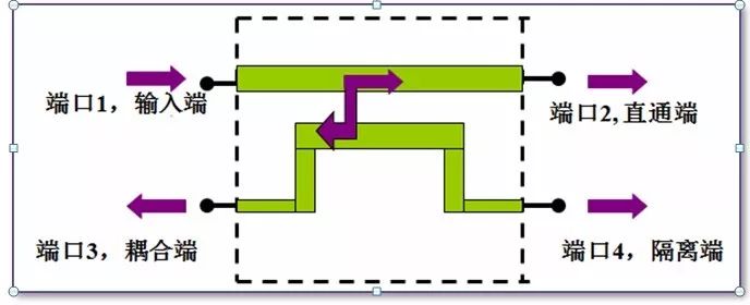
Common directional coupler schematic
An important point to note is that the amount of coupling provided by the directional coupler has a direct impact on the theoretical minimum of the insertion loss of the main transmission path. The smaller the coupling amount of the port, the lower the insertion loss. Typically, the rated power level of the coupled port is lower than the rated power level of the primary transmission path, and a fault may occur when the difference between the primary transmission path power and the coupling strength exceeds the power handling capability of the coupled port. In general, a three-port directional coupler with a precision internal termination termination is more directional than a four-port directional coupler with an external termination.
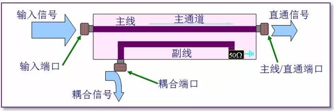
Another factor to consider is the type of termination of the directional coupler termination port. If the termination resistor is set equal to the inherent impedance of the transmission line (typically 50 ohms), the energy at the termination port can be absorbed with minimal reflection. However, when the termination port is shorted or open, or does not match the characteristic impedance of the transmission line, the energy at that port will be reflected back to the main transmission path. In addition, a fault may occur when the power of the terminating port exceeds the power limit of the terminator. This situation will become especially bad when the matched termination port fails and becomes a reflective load, which will result in a destructive power level within the primary transmission path.
Directional couplers are commonly used for test measurement applications. An example of this is to measure the input power and reflected power of the transmission line by means of a dual directional coupler or by performing multiple tests with a directional coupler. This can be used as a measure of the voltage standing wave ratio after removing the losses of the coupler itself. Other uses include, for example, signal sampling, signal injection, and power flux monitoring, where the user has to consider the loss of the directional coupler itself in order to achieve optimal accuracy.
When performing accurate measurements, it is also necessary to consider the isolation between the ports based on the quality of the directional coupler. Regardless of the coupling, there is usually a degree of leakage between the coupler ports. This amount of leakage is often referred to as isolation and is a measure of the leak-proof capability of the coupler design. The directionality of the directional coupler is the ratio of isolation to coupling coefficient and is a common performance indicator for couplers.
As with most RF/microwave devices, the exact values ​​of the device parameters do not remain absolutely consistent at different frequencies. The above coupling coefficient, insertion loss, directivity, isolation, and the like are generally frequency factors. The above factors and all manufacturing tolerances must be taken into account when making high sensitivity measurements. In addition, the directional coupler also has a parameter of operating bandwidth. At design time, trade-offs between the various parameters mentioned above are required, so the optimal design of the coupler ultimately depends on its application.
Most directional couplers do not allow DC current to pass due to port DC grounding, and only some directional couplers allow DC current to pass. For directional couplers that allow DC current to pass, it is important to keep the current below the rated value to prevent resistance losses from heating or affecting termination performance. In order to meet the target performance, all ports of the dual directional coupler (or bidirectional coupler) must be grounded. In addition, it is important that the grounding quality and the connected load be matched to the port impedance of the directional coupler.
A 90 degree or 180 degree bridge is also commonly referred to as a "coupler." Although the physical design of these devices is often very similar to a directional coupler, it works in a fundamentally different way than a directional coupler. However, since such devices can perform power distribution (3dB distribution) between the output and the coupling port, it is likely to cause damage when it is mistaken for a directional coupler with a very low coupling coefficient.
24-hour long battery life, low power consumption and high wind power are better manifestations, whether it is shopping, traveling, going to school, commuting, watching dramas, or working, it will be your intimate partner. The fan blade is designed with soft silicone, which can be automatically stopped when touched, and the protection is more comprehensive.
Outdoor Fan,Outdoor Mini Fan,Portable Small Fan,Outdoor Fan With Light
Dongguan Yuhua Electronic Plastic Technology Co.,Ltd , https://www.yuhuaportablefan.com