Keywords: stable platform, TMS320LF2407A, multi-machine serial communication, check number
A stable platform refers to a device that can make the object to be stabilized maintain the same orientation relative to the inertial space under the influence of interference, or rotate under the given torque under the given law. It is widely used in inertial measurement, weaponry and space technology. In a stable platform, servo control technology is one of the key technologies.
With the development of electronic technology and computer technology, the performance of DSP chips has been continuously improved, which has created conditions for the selection of digital servo control schemes. In the two-axis high-precision stable platform system based on DSP, two TI's motor-specific control chips TMS320LF2407A are used as controllers to control single axes respectively. F2407A contains high-speed C2XX DSP CPU core and SCI and CAN communication modules, which provides convenience for real-time communication. But it also has factors such as unfriendly human-machine interface and rich software resources that are not rich in PC, which restrict its application.
In order to give full play to the characteristics of the control chip and have a good human-machine interface to facilitate debugging and monitoring, this system uses a master-slave structure of PC and DSP. As the host computer, the PC completes the control of the DSP, the display of data results, and the human-machine interface, while the DSP completes the real-time control and uploads the real-time data. In this way, how to achieve reliable communication between multiple DSPs and PCs becomes an important issue in the implementation of the entire system. Based on the two-axis high-precision stable platform based on DSP, this paper introduces a hardware and software solution for serial communication between TMS320LF2407A and PC, and discusses the advantages and disadvantages of this method.
1 TMS320LF2407A and serial communication interface (SCI)
1.1 Introduction to TMS320LF2407A TMS320LF2407A is designed for digital motor control on the basis of TMS320 series DSP. Using high-performance static CMOS technology, the voltage is reduced from 5V to 3.3V, reducing power consumption, and the instruction execution speed is increased to 40MIPS, almost all instructions can be completed in a single cycle of 25ns, so high operation speed can be achieved by using advanced Control algorithms such as: adaptive control, Kalman filtering, and state control to improve system performance. Moreover, it has the necessary peripherals for motor control applications, such as: 32K on-chip FLASH, 2K single-access RAM, serial peripheral interface (SPI), two event management modules, 16-channel dual 10-bit A / D converter . Not only that, there is also a serial communication interface (SCI) and CAN controller module on-chip, which provides the possibility of multi-machine communication.
1.2 Serial communication interface (SCI)
The serial communication interface supports asynchronous serial digital communication with the CPU and other asynchronous peripherals that use a non-return to zero format. The receiver and transmitter of SCI are double-buffered, have their own independent control bits and interrupt bits, and can work in full-duplex mode at the same time. In order to ensure the integrity of the data, SCI checks the received data for discontinuous detection, parity, timeout, and frame errors. SCI can set up to 65000 kinds of communication speed through 16-bit baud rate selection register, and can also interface with many mainstream peripherals through RS? 232 or RS? 485. In addition, SCI also provides a multi-processor communication mode, which lays the foundation for the realization of multi-computer communication with PC.
2 A typical method of serial communication between TMS320LF2407A and PC (SCI method)
SCI has a multi-processor communication mode and can be used for multi-machine communication. The multiprocessor communication format allows the processor to effectively transfer data blocks to other processors in the same serial line communication data format of Figure 1PC and F2407A. In the same serial line, only one transmission can be performed at a time. That is, there is only one sender at a time. During the communication process, all DSPs in the serial data link set their SCI sleep bit (SCICTL1.2) to enter the receive sleep mode, so that only the address frame is detected before it is interrupted. The first frame of the data block sent by the sender is the address frame, which is read by all receivers and only has the correct address (set by the software, different DSPs can also have the same address, so that broadcast communication can be achieved) The receiver can read the subsequent data, and the other receivers do not respond, waiting for the arrival of the next address frame. Multiprocessor communication mode can be divided into idle line mode and address bit mode. The idle line mode has a delay before the address frame. There are no additional address / data bits. In the case of processing data blocks of more than 10 bytes, the idle line mode is more efficient than the address mode. The idle line mode should be used in typical non-multiprocessor communications. Moreover, for the delay of the idle line mode before the address frame, the PC process is more cumbersome, so instead of using the idle line mode, the address bit mode is used. The address bit mode, as the name implies, is to add an address / data bit (1 for an address frame and 0 for a data frame) in each byte to distinguish data from addresses. This mode is very effective for processing small blocks of data. Therefore, this method is to realize the serial communication between the DSP and the PC by making the PC simulate the communication of the DSP in the entire communication process, and adopt the address bit multiprocessor communication mode.

2.1 Communication protocol and hardware interface?
In order to achieve communication, the same communication format must be used between the PC and F2407A. Figure 1 is the asynchronous serial communication data format of the PC and the data format of the F2407A in the address bit multiprocessor mode.
As can be seen from the figure, the communication format can use 8 data bits, 1 stop bit, DSP forbid parity bit, the baud rate is 9600bit / s. The determination of the communication format of the PC is achieved by initializing the 8250 asynchronous serial communication controller. In order to achieve communication with the F2407A in address bit mode, the above communication format requirements are not enough. The address / data bits must be added to the data by specifying the parity bit. The PC sets the parity bit to 1 when sending an address frame, and sets the parity bit to 0 when sending a data frame.
Since the parity bit is prohibited, it affects the reliability of communication. To overcome this effect, a parity check method based on parity is introduced. Set a check number after every 7 bytes of data, each bit of the check number corresponds to the parity bit of each byte of data in the front, the highest bit b7 sets the parity bit of the lower 7 bits of the check number, When the data is less than 7 bytes, the corresponding position is 0.
The control command issued by the upper PC to each axis DSP is shown in Figure 2. The first byte is the DSP number, the second byte is the data length, the third byte is the command number, and the subsequent byte is the command Parameters, the data length does not exceed 10 bytes.
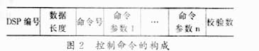
In Figure 2, the data length: indicates the number of frames from the command number to the command parameter n, n = 0, 1, 2 ... 6; the check number: each byte of data from the command number to the command parameter n The parity bit is filled in the corresponding bit of the check digit. For example, the parity bit of the command number is filled in the b0 bit of the check digit, and so on, the b7 bit is filled in the parity bit of the check digit.
The data uploaded by the lower DSP is 8 bytes, the first 6 are real-time data, and the 7th is the receiving state number, which indicates the state of the DSP receiving, and the receiving state number is set every time the data reception ends. The 8th byte is still the check digit.
Because the adopted RS-232 communication protocol is point-to-point communication, there is no conflict detection and arbitration mechanism, and the application environment is multi-machine communication, it is necessary to control access to the bus. The master-slave communication method is adopted here, that is, the host PC controls the bus access. The host computer sends instructions and data to the slave. When the slave is required to upload data, it sends an upload instruction and waits for the data upload from the slave. During this period, do not send any instructions to send data to avoid conflicts, resulting in communication failure.
On the hardware, because RS-232 is negative logic, its low level "0" is between + 5V- + 15V, and its high level "1" is between -5V--15V. The F2407A is designed with a low voltage, the input voltage is 3.3V, the output high level "1" is between 2.4-2.8, and the low level "0" is between 0.4-0.8. Obviously, this does not match the RS-232 protocol, and level logic conversion must be performed. We use the simplest mode of Modem (3-wire system). In communication, both sides are regarded as data terminal equipment, and both sides can send and receive (full-duplex mode). The hardware interface diagram is shown in Figure 3.

2.2 Software implementation?
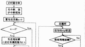
For the upper PC, set a regular interrupt to send commands to the lower DSP through the serial communication port COM1 every 20ms. If the command that requires the lower computer to send data is sent, wait for the data upload to end and verify the data. If the verification fails, send a retransmission instruction and continue to wait for the data to be uploaded, repeated 3 times. If it still fails, it indicates that the communication has failed and exits. The lower DSP receives data by means of inquiring. It verifies the received data. If the verification is wrong, the receiving status number is set to false. DSP data transmission is controlled by the host computer, sending fixed-length data (including real-time data and status data, 7 bytes in length), adding a check number to the end of the data to achieve serial communication with the host computer. When the host computer reads the lower DSP's last receiving status error, it will send the last command again. The upper computer can use Visual C ++, and the lower DSP can use C language and assembly language mixed programming, which is convenient to implement and has high efficiency. Fig. 4 gives the flow chart of the timing interrupt of the upper computer and the receiving data of the lower DSP respectively.

3 Conclusion?
The SCI method has a lower implementation cost, and only requires a level logic conversion chip and a serial communication line to realize the serial communication between the TMS320LF2407 and the PC. Although the parity bit is forbidden, due to the parity method based on parity check, the bit error rate measured by actual operation is still within the required range, achieving high-speed reliable communication and meeting the real-time communication requirements. However, there are certain limitations, for example: due to the limitation of RS? 232 protocol, the communication distance is only about 15m, there is no conflict detection and arbitration mechanism, only the use of PC to control the bus access [FL (2K2) line, which reduces The use efficiency of the PC and the use efficiency of the bus. These problems can be further solved in future research. For example, the RS? 485 protocol can be used to increase the communication distance, and the CAN controller on the 2407A can be used to pass the CAN bus. Solved, but there are some shortcomings in the implementation. In general, the multi-machine communication realized by the SCI method is a high-speed real-time communication method with high cost performance, and has a wide range of application fields.
references?
1 Edited by Liu Heping. TMS320LF240X DSP structure, principle and application. Beijing: Beijing University of Aeronautics and Astronautics Press, 2002
2 Hu Guang et al. Multi-computer serial communication between PC and TMS320LF240 under Windows 98. Electronic Technology, 2001 (3)
3 Pan Minglian et al. Principles of Microcomputers. Beijing: Electronic Industry Press, 1994
Fiberglass Duct Rodder are composed of fiber glass rod which was extruded by fiber glass and high strength resin at high temperature. This type of rod has high tensile strength and flexibility. It was covered by a high density polyethylene engineering plastic as its protect layer(High Density polyethylene (Grade: for the insulating and jacketing of Telecommunication Cables) is used in the outer diameter coating.), which make duct rodder cover sliding on surface, durable, corrosion resistant and has good insulation performance, which make them safe for use in cable occupied duct.
And moving type fiberglass duct rodder will equipped with different size reel according to the length of rod. There are wheels on the reel, which make it convenient for moving.
Features and Benefits:
-
Light weight, durable, resistance to acid, alkali, aging resistant, corrosion resistant.
2-High tensile strength and bending properties, which make it to go through narrow pipes easily.
3-Good temperature adaptability, the product will not soften in hot weather/nor become brittle in cold weather. Its usability will not be affected by temperature.
4-Outer protect layer are made of high density polyethylene engineering plastic, which has good anti-UV capability.
5-Cover was coated with long-term UV-resistant polyethylene.
6-Its surface has the advantage of smooth, wear-resistant and long service life.
7-There are meter marks on the protect layer of duct rodder, which can be used for measuring distance. Marks are printed by professional printing machine, which has the advantage of strong adhesion, clear writing, waterproof, anti-ultraviolet, it can be still clear even after using many times.
8-There are several kinds of colors for the rod for your chosen.
Fiberglass Rodder,Fiberglass Duct Rodder,Fiberglass Conduit Rodder,Duct Push Rod,Fiberglass Duct Rod,Conduit Rod
NINGBO BEILUN TIAOYUE MACHINE CO., LTD. , https://www.spool-manufacturer.com