The mathematical process of switching mixing is deduced in detail, and the specific implementation is given on the basis of this. The theory and practice show that the mixing mode based on analog switch can overcome the defects of the traditional nonlinear component or multiplier mixing mode, eliminate the influence of the local oscillator signal, and retain the parameter information of the input signal to the utmost.
*Fund Project: National Natural Science Foundation of China (11602300)
Usually the mixing is achieved using non-linear components or dedicated multipliers, which inevitably introduce amplitude and phase information of the local oscillator signal into the output signal, which is often undesirable. And whether nonlinear components or dedicated multipliers generate a lot of interference and distortion, including interference whistling, parasitic channel interference, cross modulation distortion, and intermodulation distortion, all have adverse effects on receiver performance. The switching mixing method can effectively suppress the influence of the above factors.
1 mixing principle
Mixing circuit, also called frequency converter (Mixer, Convertor), is an important part of superheterodyne receiver, which can realize undistorted spectrum shifting [1].
There are many ways to achieve mixing, and the most common is a multiplying circuit, which can be implemented using a non-linear device or a dedicated integrated circuit multiplier. Suppose the two input signals of the multiplier are:
V1=Acos(ω1t+φ1), v2=Acos(ω2t+φ2),
Then its output is:
Vo=AB2{cos [(ω1+ω2)t+(φ1+φ2)]+cos[(ω1-ω2)t+(φ1-φ2)](1)
For the receiver, usually only the low-frequency component of the signal is concerned, so the low-frequency component [2] can be obtained by the first-stage low-pass filter, and its output can be written as:
Vo=AB2cos[(ω1-ω2)t+(φ1-φ2)](2)
It is obvious that the multiplier output signal amplitude, phase and frequency are related to both input signals.
For the receiver, only the influence of the received echo signal parameter changes on the receiver output is concerned, and it is not desirable to introduce too many parameters of the local oscillator signal. At the same time, since the multiplier is a nonlinear device, it will generate a lot of interference and distortion, including interference whistling, parasitic channel interference, cross modulation distortion, mutual modulation distortion, etc., and when the amplitude of the input signal increases, the amplitude is multiplied. As a function, the output signal is likely to be limited, resulting in distortion [3]. These factors can greatly affect the performance of the receiver, so the multiplier is not the best choice for implementing the receiver mixing circuit. Switching mixing can effectively overcome analog multiplier defects.
2 switching mixing principle
Also assume that the input signal and the local oscillator signal are:
V1=Acos(ω1t+φ1),
V2=Acos(ω2t+φ2),
Now take the square wave signal v'2 with the same frequency as v2:
![]()
Expand it into a Fourier series to get:
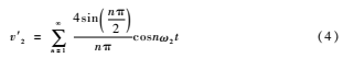
Obviously, v'2 is a set of multiple harmonics with ω2 as the fundamental wave [4]. Therefore, it is also possible to use v1 and v'2 to mix and then take the fundamental wave to obtain the result of mixing v1 and v2.
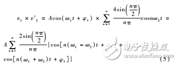
Then the mixing of the signal v1 and the square wave signal v'2 can be written as:
Then through the low-pass filter, filtering the sum frequency and the difference frequency higher harmonics can be obtained:
It can be seen from equation (6) that the final result after mixing is that the amplitude and phase are only related to the input signal, and the frequency is the signal of the difference between the input signal and the local oscillator signal. Obviously mixing in such a way can maximize the original information of the signal while minimizing the effects of the local oscillator signal.
3 switching mixer implementation
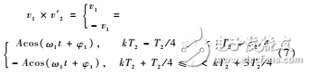
Based on the above switching mixing principle, the mixing of v1 and v'2 can be expressed as:
@T3VI}N_7@(07]N1}R8`(AH.png
It can be seen from equation (7) that the mixing of v1 and v'2 is equivalent to outputting v1 during the positive level of v'2, and outputting -v1 during the negative level of v'2, so the analog switch can be used to achieve the mixing. Frequency [5]. The specific implementation method is shown in Figure 1.

The input signal v1 is divided into two paths, one is v1, the other is -v1, and two analog switches are respectively input. The on/off of the analog switch is controlled by the signal v'2, and the upper analog switch is turned on at the positive level, and the corresponding output is v1. At the negative level, the following analog switch is turned on, and -v1 is output accordingly. Obviously, the result is in agreement with equation (7). Thus, multiplication of v1 and square wave signal v'2 is achieved, and signal mixing is completed. Obviously the output signal amplitude and phase in this way depends only on the input signal v1 and is independent of the square wave signal v'2. Its waveform is shown in Figure 2.

The mixed output results contain higher harmonics, so subsequent low-pass filtering is required to obtain the difference signals of v1 and v2.
4 Conclusion
It can be seen from the above analysis that the switching mixing can also achieve two-signal multiplication, and the phase and amplitude of the output signal are only related to the input signal, and are independent of the local oscillator signal, so it is more conducive to the detection of the input signal by the subsequent circuit and related parameters. Identification process.
For multi-input receiver systems, the switching mixing method is more conducive to eliminating parameter distortion introduced by the inconsistency of the local oscillator signal, and improving the receiver's ability to recognize and process the effective target signal.
Kitchen Range Hood Motor,Range Hood Motor,Kitchen Range Hood,Range Hood Fan Motor
WUJIANG JINLONG ELECTRIC APPLIANCE CO., LTD , https://www.jinlongmotor.com