This article introduces the small signal model of the Buck circuit's continuous inductor current.
Small Signal Model for Buck Circuit Inductor Current ContinuousFigure 1 shows a typical Buck circuit. To simplify the analysis, assume that the power switches S and D are ideal switches, the filter inductor L is the ideal inductor (resistance is 0), and the circuit operates in continuous current mode (CCM). Re is the equivalent series resistance of the filter capacitor C, and R0 is the load resistance. The positive direction of each state variable is defined as shown in the figure below.
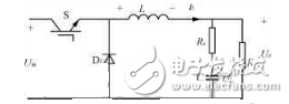
Figure 1 Typical buck circuit
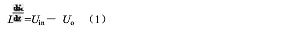
When s is on, the equation of state for the inductor column
When s is disconnected, when the D1 is continuously turned on, the state equation becomes

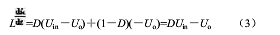
When the duty ratio is D, during the switching period, Equations (1) and (2) last for DTs and (1-D)Ts respectively (Ts is the switching period), therefore, the average of the inductance in one cycle The equation of state is
At steady state, 7=0, then DUin=Uo. This shows that the output voltage is a constant at steady state, and its magnitude is proportional to the duty cycle D and the input voltage Uin.
Since each state variable of the circuit always fluctuates around the steady state value, it is obtained by equation (3).

Equation (4) is formed by the steady state value of equation (3) plus a small signal fluctuation value. The amount marked as a wavy is the amount of fluctuation, and d is the amount of fluctuation of D. Equation (4) minus equation (3) and omitting the product of the two fluctuations

From Figure 1, there are
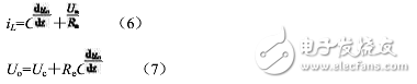
Equations (6) and (7) are established regardless of the state in which the circuit operates. Available from equations (6) and (7)
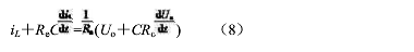
The derivation of equation (8) assumes Re "R. Due to steady state  =0,
=0,  =0, the steady state equation from equation (8) is iL=Uo/Rg.
This means that the average value of the inductor current flows through the load at steady state. Add small signal fluctuations to each variable in equation (8)
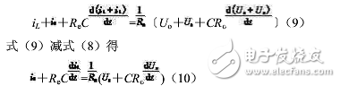
Performing the Laplace transform of equation (10)
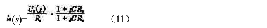
It is generally believed that the input voltage is constant in the switching frequency range, and it can be assumed that Us=0 and substituted into equation (5), and the equation (5) is transformed by Laplace.

From equation (11), equation (12)
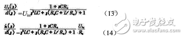
Equation (13), Equation (14) is the control of the Buck circuit when the inductor current is continuous - the output small signal transfer function.
Wire On Tube Condenser air cooled condenser
The condenser which is cooled down of the natural air. this Condenser category as a natural convection type of air cooled condenser which cooled, by the help of natural air.
In construction, it consists of a copper tube Or coil and maybe iron or steel coil upon which iron or steel material of fitted Or soldered together. the flows through the compressed vapour refrigerant in the coil then coil are heated up and supplies it to iron meterial. This iron meterial rejection of the heat, to the atmospheric air.
This type of condenser used in Domestically. For example of the Refrigerators, it's located at the background of the Refrigerators.
Fridge Condenser Unit,Wire On Tube Condenser,Wire And Tube Condenser,Refrigeration Wire Tube Condenser
FOSHAN SHUNDE JUNSHENG ELECTRICAL APPLIANCES CO.,LTD. , https://www.junshengcondenser.com