In the past two years, with the rise of technologies such as cloud computing, big data, computing virtualization, etc., along with everyone's yearning for “cloudâ€, it has accelerated the maturity and application of network virtualization technology. It can be said that the current IT infrastructure network has no "cloud", switch virtualization technology has become the technology of choice for new network architecture.
So what is the deployment principle of switch virtualization? How to deploy in the real network structure? What enhancements and innovations did virtualization 2.0 do? Today we will unveil the mystery of switch virtualization technology and fully understand the technology;
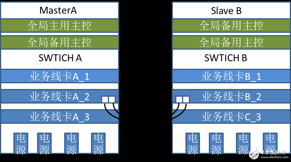
Now let's look at the deployment mode of high-end switch virtualization technology that is common in the industry, as shown in Figure 1.
(figure 1)
Referring to the two device deployment modes, the two devices are member "master" and member "slave" devices. The virtualized interconnection is mainly realized by directly connecting the physical ports of the high-speed line cards through link bundling. Figure 1.
Interconnected links are called VSL (Virtual Switching Link) links. Considering the price/performance ratio, there are two main deployment methods:
Mode 1: Directly through the high-speed optical fiber interconnection, the rate is high, the member deployment distance is not limited, and it is widely used in scenarios such as multi-core nodes and disaster recovery interconnection;
Mode 2: Connected through a dedicated connection cable, the cost is low, and the member distance is limited. It is suitable for deployment in the same equipment room and the same cabinet.
After the device virtualization architecture is deployed, from the management point of view, two or more devices are “integrated†into one device. They share a routing table and a forwarding table. It is equivalent to having one deployment and multiple masters. The "super" switch of the service line card, all the functions are deployed in the same way as a single device configuration.
The above network structure deployment model, we call it VST 1.0 (Virtual Switching Technologies). At present, it is widely deployed in the building LAN, campus network and data center, and the application is mature. At the same time, as the market deployment increases, the application coverage increases, and the maintenance experience accumulates, we also find that the above deployment mode has further optimization and improvement in technology. "innovation" potential;
For example, the virtualized connection between devices is realized by the VSL interconnection in the middle of the device, which inevitably appears:
â– The link bandwidth is insufficient, which easily forms a bandwidth forwarding bottleneck.
â– Normal data forwarding packets and virtualized management packets are transmitted on the same physical channel. Data packets are prone to occupy bandwidth resources, causing hidden risks in the architecture.
In order to solve the above two problems, the solution has been adopted: on the basis of maximizing the VSL physical link, a complex QoS guarantee mechanism is superimposed on the VSL link, and the management packet processing is preferentially guaranteed.
1. QoS function deployment introduces complex software function design, resulting in bloated functional modules and increased structural complexity;
2. Qos itself has not fundamentally solved the resource conflict problem.
In order to fundamentally solve the resource conflict problem caused by the traditional virtualized deployment architecture, Maipu has upgraded and optimized the original high-end virtualization technology VST1.0 to form the current VST2.0 technology.
The product is manufactured in accordance with GB4004-83, JB/T7600.3-94 and DlN46395 standards. Its common carbon steel Q235 thin steel plate punched into corrugated type serves as the lateral plate; And its mandrel and major body are supported by four-groove reinforcing steel bars. The product has the characteristics of not only strengthening the strength of bobbin, but also having light weight of bobbin, which can be used for buncher, stranding machine, extruder, cabling machine and armouring machine.
| Serial Number | Specification Model | Lateral Plate Diameter D1 | Major Diameter D2 | Axle Hole Diameter D4 | Carrying Hole Diameter D5 | Center Distance E of Axle Hole and Carrying Hole | External Width L1 | Internal Width L2 |
| 1 | 800 | 800 | 400 | 80 | 40 | 160 | 600 | 500 |
| 2 | 1000 | 1000 | 500 | 80 | 40 | 160 | 750 | 630 |
| 3 | 1120 | 1120 | 560 | 80 | 40 | 160 | 850 | 710 |
| 4 | 1250 | 1250 | 630 | 80 | 40 | 160 | 950 | 800 |
| 5 | 1400 | 1400 | 710 | 80 | 65 | 300 | 1060 | 900 |
| 6 | 1600 | 1600 | 800 | 80 | 65 | 300 | 1180 | 1000 |
| 7 | 1800 | 1800 | 1000 | 100 | 65 | 300 | 1320 | 1120 |
| 8 | 2000 | 2000 | 1120 | 1235 | 65 | 300 | 1500 | 1250 |
| 9 | 2240 | 2240 | 1250 | 125 | 65 | 300 | 1700 | 1400 |
| 10 | 2500 | 2500 | 1500 | 125 | 65 | 300 | 1900 | 1600 |
| 11 | 2800 | 2800 | 1800 | 140 | 65 | 300 | 2120 | 1800 |
| 12 | 3150 | 3150 | 2000 | 160 | 65 | 500 | 2300 | 2000 |
| 13 | 4000 | 4000 | 2800 | 200 | 80 | 500 | 2300 | 2000 |

Corrugated Wire Spool, Corrugated Cable Spools, Cable Spools For Sale
NINGBO BEILUN TIAOYUE MACHINE CO., LTD. , https://www.spool-manufacturer.com