Flyback: A flyback switching power supply is a switching power supply that uses a flyback high frequency transformer to isolate the input and output circuits. "Reverse" means that when the switch is turned on, when the input is high, the inductance in series in the output line is discharged; on the contrary, when the switch is off, when the input is high, the output is The series inductance in the line is charged.

Working principle: The polarity of the primary and secondary windings of the transformer is opposite. This is probably the origin of the Flyback name: a. When the switch is turned on, the primary inductor current begins to rise. At this time, due to the relationship of the secondary end, the output The diode is turned off, the transformer stores energy, and the load is powered by the output capacitor. b. When the switch is turned off, the inductance of the primary side of the transformer is reversed. At this time, the output diode is turned on, and the energy in the transformer supplies power to the load via the output diode, and the capacitor is charged to supplement the energy just lost. Evolution of flyback circuits: Can be seen as isolated Buck/Boost circuits:
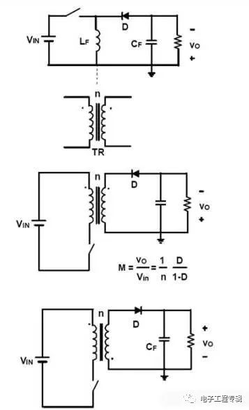
In the flyback circuit, the output transformer T has the function of storing energy in addition to electrical isolation and voltage matching. The former is the property of the transformer, and the latter is the property of the inductor. Therefore, some people call it an inductor transformer, sometimes I also Call him an asynchronous inductor.
Forward power
The transient control characteristics and output voltage load characteristics of the output voltage of the forward-type transformer switching power supply are relatively good. Therefore, the operation is relatively stable, and the output voltage is not easy to generate jitter. In some occasions where the output voltage parameters are relatively high, frequently used.
The so-called forward transformer switching power supply means that when the primary coil of the transformer is being excited by the DC voltage, the secondary winding of the transformer has just the power output.
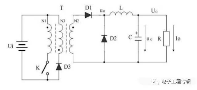
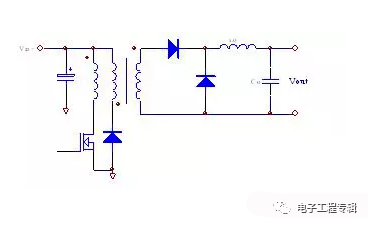
Single-ended forward type:
Double tube forward type:

As can be seen from the above three figures, the flyback transformer can be regarded as an inductor with a transformer function and is a buck-boost circuit. The forward transformer is only a transformer function, and the whole can be seen as a buck circuit with a transformer. The secondary side of the first rectifier diode is connected to the negative terminal of the electrolytic capacitor is a counterattack, and the inductor is forward.
In general, the principle of positive reaction is different. The positive is that the secondary work also works. The secondary does not work with the freewheeling inductor, which is usually CCM mode. The power factor is generally not high, and the input and output are proportional to the duty cycle. Flyback is the primary work, the secondary does not work, and the two sides are independent. In general DCM mode, the theoretical unit power factor is used, but the inductance of the transformer will be relatively small, and the air gap needs to be added, so it is generally suitable for small and medium power situations. The power book will have a specific introduction and design formula.
The forward transformer is ideal and does not store energy, but since the magnetizing inductance (Lp) is a finite value, the exciting current causes the core B to be large. To avoid flux saturation, the voltage transformation requires the auxiliary winding to perform magnetic flux reset; the flyback transformer The working form can be regarded as a coupled inductor; the inductor first stores energy and then discharges energy. Since the input and output voltages of the flyback transformer have opposite polarities, the secondary can provide a reset voltage of the magnetic core after the switch is turned off, so that the flyback transformer does not need to additionally increase the flux reset winding.
Main difference
The main difference between positive flybacks is that high frequency transformers work differently but they are in the same quadrant. The forward is that when the primary switch of the transformer is turned on, the energy is transmitted to the load. When the switch is turned off, the energy of the transformer is demagnetized by the magnetic reset circuit. The flyback is the opposite of positive, storing energy to the transformer when the primary switch is turned on. But the energy is not added to the load. When the switch is turned off, the energy of the transformer is released to the load side. Forward switching power supply, the latter diode is a free-flow diode, the general output part will add an additional energy storage inductor, the most important difference between forward and flyback is that the phase of the primary and secondary of the transformer is reversed.
Maximum difference
The biggest difference between forward and flyback work is that when the switch is turned off, the forward output mainly relies on the energy storage inductor and the freewheeling diode to maintain the output, while the flyback output mainly relies on the transformer secondary to release energy. Maintain output. The forward circuit should not be used for multi-channel output. The forward circuit must be pulse-width adjusted for voltage regulation. The string inductance must be after the secondary rectification. Otherwise, the output voltage is mainly determined by the input, and the pulse width has little effect. The pulse width only affects the output pattern. wave. If the forward circuit is used as a multi-channel output principle, if there is no inductor in each output, there is no voltage regulation on the input change, and there is no safety of the switching power supply. If each inductor is added: then the output voltage is theoretically related to the magnitude of the load, and the loop that does not participate in the feedback is not correct.
The flyback circuit is in principle suitable for multiple output regulation. The flyback circuit first stores energy, and then supplies the energy to each channel according to the voltage ratio of each channel. First, it can be considered that the output ratio of each channel is constant (the actual error is seen below), and who needs more for the current. Principle allocation.
About feedback
The way to be fed back is always accurate because it is based on looking for him to feedback, but the feedback must be a little load all the way. Otherwise it will increase the imbalance between the outputs. The multi-channel weighting can be used for feedback, so that the vector sum of the errors can be zero. The popular point allows the error to be balanced among the paths, and the weight of which way is significant, and the accuracy of which way is high. The transformer complies with each transient voltage ratio equal to the coil ratio, which is one of the most used conditions in understanding.
About switching power supply
The forward mode is the secondary circuit of the transformer when the switch is turned on. The flyback mode is the secondary circuit of the transformer when the switch is turned off (the switch is cut off, the main stage energy is transferred to the secondary, the secondary work switch is closed, and the main inductor is closed. Store energy). Forward switching power supply output must have freewheeling diodes and flyback type (their transformer winding method is different. Flyback transformer first pole working time is opposite and positive initial pole working time is the same) positive and negative There are more devices than the biggest ones, although it seems that there are not many, but it is essential, and the cost is very high. The circuit uses a larger energy storage filter inductor and a freewheeling diode than the flyback transformer switching power supply. The output voltage of the forward-type transformer switching power supply is modulated by the duty cycle, which is much lower than that of the flyback-type transformer switching power supply. Therefore, the forward-variable transformer switching power supply requires a higher error signal amplitude for regulating the duty cycle. The gain and dynamic range of the error amplifier are also large.
Forward-type transformer switching power supply In order to reduce the excitation current of the transformer and improve the working efficiency, the volt-second capacity of the transformer is generally larger, and in order to prevent the counter-electromotive force generated by the primary coil of the transformer from breaking down the switching tube, the forward-type transformer switching power supply The transformer has one more back electromotive force absorption winding than the transformer of the flyback transformer switching power supply. Therefore, the transformer of the forward type switching power supply has a larger volume than the transformer of the flyback type switching power supply.
A further disadvantage of the forward-type transformer switching power supply is that the counter-electromotive voltage generated by the primary coil of the transformer is higher than the counter-electromotive voltage generated by the flyback switching power supply when the control switch is turned off. Because the general forward-type transformer switching power supply works, the duty cycle of the control switch is taken to be about 0.5, and the duty cycle of the flyback-type transformer switching power supply control switch is relatively small.
Application difference
The forward-type transformer does not accumulate energy and only bears the coupling transmission. The flyback transformer needs to accumulate the energy in the turn-on process itself, and then release it during the turn-off process: the forward winding is in phase, and the flyback winding is inverted; The excitation transformer does not need to adjust the inductance value, and the flyback type needs to be adjusted. In the forward operation, there is a residual magnetism to prevent the saturation from degaussing the circuit, and the energy storage coil and the freewheeling diode are not required for the self-recharging. The flyback type is not used.
Flyback is mainly used in the case of 150-200 watts, and positive is used in the range of 150w to several hundred watts. The reason why the reaction is broader is because the power supply below 100w in our daily life is more common, and the application is more common, so it is more extensive. The principle is that one transforms through the energy storage and then through the transformation ratio, and the other is to transform the pressure directly through the transformation ratio. The positive primary windings are positive at the same end, so they are called positive, the flyback is positive, and the negative is called reverse.
The flyback type can be used for low power, low cost, and relatively simple debugging, so it is commonly used in low power power supplies. The difference between them: In terms of the main transformer, it is necessary to increase the degaussing winding. Of course, some two diodes are used to demagnetize the main winding. In any case, the forward power supply must increase the degaussing circuit. The flyback does not increase the output energy storage inductance because the energy can be stored in the secondary coil, the positive excitation must increase the output energy storage inductance, and the rectifying portion needs to increase the freewheeling diode.
Lead Acid Replacement Battery,Lithium Iron 24V Battery,Lithium Iron 12V Battery,Lithium Ion Phosphate Battery
Shenzhen Unitronic Power System Co., Ltd , https://www.unitronicpower.com