In the design of high temperature operating circuits, you must consider the variation of IC parameters and passive components over a wide temperature range, with particular attention to their characteristics at extreme temperatures to ensure that the circuit can operate within target limits.
For example, offset and input offset drift, gain error, temperature coefficient, voltage rating, power dissipation, board leakage, and inherent leakage of other discrete devices such as ESD devices and overvoltage protection devices. For another example, when the high source impedance is connected in series with the input of an amplifier, the unwanted leakage current (not the bias current of the amplifier itself) will cause an offset, which in turn causes a bias current measurement error (Figure 1).
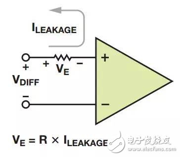
Figure 12. How bias current and leakage current produce offset error
Tips
In all cases, high temperature operation can increase board leakage caused by contamination such as flux, dust and condensation. A reasonable layout helps minimize this effect by providing enough space between sensitive nodes, such as separating the amplifier input from the noisy supply rail.
The standard pinout method for op amps and instrumentation amplifiers is to place one of the inputs near the negative supply terminal. This approach greatly reduces the resistance to solder residue after PCB assembly, and these flux residues increase leakage. To reduce leakage and increase high frequency CMRR, the high temperature device AD8229 uses the same high performance pinout as other ADI precision instrumentation amplifiers (Figure 2).
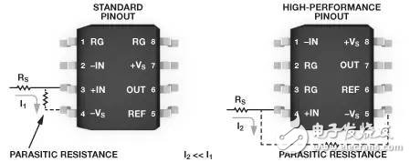
Figure 2. Device pinout improvements help minimize parasitic leakage
Diodes, transient voltage suppressors (TVS), and other semiconductor devices leak exponentially with increasing temperature, and in many cases are orders of magnitude higher than the amplifier's input bias current. In these cases, you must ensure that leakage at extreme temperatures does not degrade the circuit specification beyond the required limits.
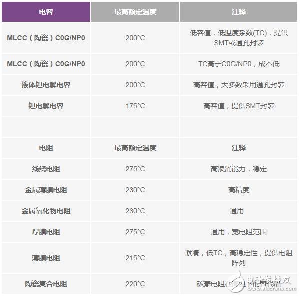
Today, there are a variety of passive components available for use in high temperature work environments. Resistors and capacitors are common in a variety of circuit designs. Table 1 lists some of the devices available on the market.
Table 1. Examples of High-Temperature Resistors and Capacitors
Tips
If the surface mount device is placed against the PCB, leakage between the pins can easily occur because the solder residue remains at the bottom of the board after the assembly is completed. These flux residues absorb moisture, increasing the conductivity at high temperatures. At this time, parasitic resistance (characteristics are difficult to predict) occurs in surface mount devices, which may cause other circuit errors. To solve this problem, consider using larger chips, gull-wing pins, or through-hole devices in particularly sensitive circuit areas. Finally, add an effective board cleaning step (usually with ultrasound or saponifier) ​​before the end of the assembly process, and useless residues can be removed almost completely.
You must keep in mind the thermal management requirements when designing systems that operate in harsh environments. Even when high-temperature dedicated devices are used, the self-heating effect associated with their power consumption should be considered. For example, the AD8229's guaranteed operating temperature is as high as 210 ° C, which is equivalent to a small output current load. The extra power consumed by driving high load or permanent fault conditions (such as output shorts) increases the junction temperature beyond the maximum rating of the device, greatly reducing the operating life of the amplifier. Be sure to follow the recommended heat dissipation guidelines and pay attention to adjacent heat sources such as power conditioners.
Even at high temperature resistance, the rated power is reduced above 70 °C. Pay special attention to the resistance temperature rating at the target operating temperature, especially if the power consumption is quite large. For example, suppose a resistor rated at 200 °C operates at an ambient temperature of 190 ° C. If it has a self-heating of 20 ° C due to power consumption, it still exceeds the rated value.
Although many passive components can withstand high temperatures, their construction may not be suitable for long-term environments with both shock and high temperatures. In addition, high temperature resistors and capacitor manufacturers also specify their operating life at a given temperature. Keeping the operating life specifications of all devices in place is critical to building a highly reliable system. Finally, don't forget that many devices rated at high temperatures may need to be derated to maintain long-term operation.
Case study: Draw a thermal gradient in the oven
The AD8229 and ADXL206 (dual-axis accelerometers) operate in a lightweight, safe, high-temperature environment and can be demonstrated as two suitable devices for high temperature applications. The demonstration uses a small electric oven with a rotating assembly with a high temperature PCB on top and continuous operation. The heating element in the oven is located near the top. This design creates a large temperature gradient in the oven. The rotation mechanism is used in experiments where temperature and position are measured simultaneously.
The AD8229 is responsible for conditioning the signal from the K-type thermocouple, which is constantly rotating in the oven. The thermocouple probe extends approximately 6 inches from the PCB for better measurement of oven temperature changes. At the same time, the ADXL206 is responsible for measuring the angle of rotation. The three signals (temperature gradient, x-axis acceleration and y-axis acceleration) are transmitted through a slip ring (rotary connector) rated to high temperature operating conditions. The slip ring can be connected to a non-rotating cable that is connected to a data acquisition board outside the oven. Since the "cold junction" is located inside the oven, an additional thermocouple can be used to provide a static reference for the internal temperature. The AD8495 thermocouple amplifier (also outside the oven) uses its integrated cold junction compensation to condition the additional thermocouple signal.
The board in the oven is located on a rotating assembly near the center where the temperature is approximately 175 °C. The circuit board structure is made of polyimide material. The traces on the copper layer have a minimum width of 0.020 inches to improve the connection of copper to the prepreg (Figure 3). The device is connected using standard HMP solder (5/93.5/1.5 tin/lead/silver) and is connected to the board and slip ring using a Teflon coated wire.
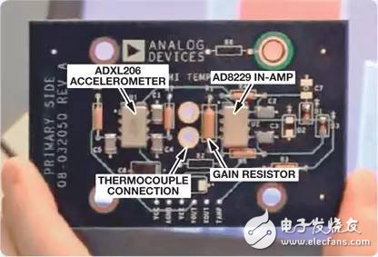
Figure 3. High temperature PCB mounting the device
All precision components are mounted in through-holes. The gain of the instrumentation amplifier is set by a 25 ppm/°C metal film resistor. The amplifier operates at high gain, so the trace length of the amplifier to the gain resistor should be as short as possible to minimize copper resistance (4000 ppm/°C TC). The thermocouple and amplifier interface is located in the center of the board to maintain temperature stability during rotation. The thermocouple pins should be as close as possible to eliminate unwanted thermoelectromotive effects at the junction.
High temperature tantalum capacitors and C0G/NP0 capacitors decouple the power supply and act as a filter for the accelerometer output.
The computer processes data from four different sources: the angle of rotation (rectangle x and y components), the internal temperature gradient, and the reference temperature. The temperature gradient can be plotted by combining the above measurements (Figure 4). The analysis showed that the temperature change reached 25 °C. As expected, the highest temperature is near the heating element next to the top of the oven's back wall. Due to natural convection, the top of the oven is the second hot area inside the oven. The lowest temperature is measured when the thermocouple is opposite in position to the heating element.
The experiment shows in a simplified form how high-temperature devices integrated in the recording system extract valuable information when operating in harsh environments.
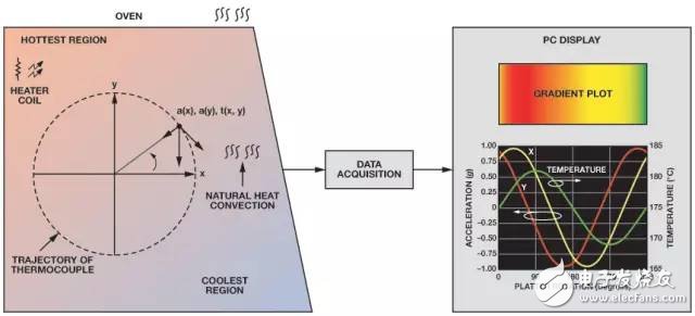
Figure 4. High temperature demonstration
in conclusion
Many (both mature and emerging) applications require devices that can operate in extreme high temperature environments. In the past, designing such a reliable system was difficult due to the lack of devices rated to operate in such harsh environments. Now, ICs and support devices that work in these environments have emerged, saving engineering time and reducing the risk of failure. Using this new technology and following a high-temperature design approach, high-performance systems can work reliably in more extreme environments than previously viable environments.
door opener keychain no touch,no touch keychain,no touch tool keychain,no touch keychain bulk, no touch keychain wholesale
Shenzhen Konchang Electronic Technology Co.,Ltd , https://www.konchangs.com