The TRF6900 is a single-chip RF transceiver from TI that integrates a complete transmit and receive circuit, making it ideal for two-way wireless transmission of data in the ISM band. The structure, principle, characteristics and application circuit of TRF6900 are introduced.
The TRF6900 is a single-chip RF transceiver chip from Texas Instruments that integrates a complete transmit and receive circuit. Its operating frequency range is 850~950MHz, the power supply voltage range is 2.2~3.6V, the RF output power is up to +5bBm, while the standby mode current consumption is only between 0.5μA~5μA, and the TRF-6900 uses high throughput rate16. -bit RISC architecture with a maximum rate of 8 MIPS. In addition, the transceiver also has FM/FSK modulation mode and uses a three-wire serial interface, so it can be easily connected to the microcontroller and can be used for two-way wireless transmission of data in the ISM band. It is suitable for computer telemetry remote control system, handheld battery-powered operating system instrumentation equipment and security system.
Basic structure and characteristics
The TRF6900 is available in a 48-pin PQFP package with the pin functions listed in Table 1. The TRF6900 is mainly composed of a combination of a transmitting circuit and a receiving circuit. The transmit circuit includes an RF power amplifier, a phase-locked loop, a voltage-controlled oscillator, a programmable direct digital synthesizer and low-power control logic, and a serial interface circuit. Receiver circuit includes low noise amplifier, RF buffer amplifier, RF mixer, local oscillator buffer amplifier, first stage IF amplifier, second stage IF amplifier limiting, FM/FSK demodulator, low pass filter amplifier / post detection The amplifier, data limiter, and received signal strength indicate the circuit such as the indicator.

In the transmit circuit, the TRF6900 is programmed with a 3-wire unidirectional serial bus (CLOCK, DATA, STRLBE). In the 24-bit shift register in the on-chip microcontroller, if STRLBE is set high, the programming information will be loaded into the selected latch to complete the DDS mode, modulator, and PLL settings. When the transmitted data enters DOS through the TX DATA terminal, the digital signal can be converted into an analog signal by a DOS circuit through an 11-bit digital-to-analog converter sine wave former. The input oscillator fref of the reference oscillator is 15 ~ `26MHZ, the programmable DOS splitter ratio is 0~4194303 bits, the resolution is Δf=Nfref/224, the FSK modulator registration ratio is 0~1020bits, and the resolution △f=Nfref /222. The clock circuit in the chip uses an external crystal oscillator (25.6 ~ 26MHZ) to generate the reference frequency required by the circuit. The local oscillator uses a phase-locked loop (PLL) method, which consists of a frequency synthesizer, an external passive loop filter, and a voltage-controlled oscillator. The frequency range of the voltage controlled oscillator is 850 ~ 950MHZ. The output power of the RF power amplifier is up to +5bBm.
In the receiving circuit, the low noise amplifier has a gain of 13bB and a noise figure of 3.0 bB. The receiving circuit has two modes: standard mode and recursive mode. In order to obtain maximum sensitivity at low RF input levels, the standard mode should normally be selected, while at high RF input levels, the low gain mode should be selected. The mixing uses a conventional double balanced Gilbert-Cell mixer structure with an output impedance (MIX-OUT) of 330 Ω and allows a 330 Ω ceramic filter to be directly connected to the terminal MIX-OUT. The first stage IF amplifier has an amplification gain of approximately 7Bb and an input and output impedance of 330Ω. The secondary IF amplifier and limiter per day have an amplification gain of approximately 80Bb and an input impedance of 330Ω, with a frequency range of 10 to 21.4MHz limiter. The output is connected to the FM/FSK's mediator. When the frequency range is from 10 MHz to 21.4 MHz, the slope of the received signal strength indicator should be 19 Mv/dB. The FM/FSK demodulation circuit is used to perform demodulation of FM or FSK signals. The demodulator output bandwidth is 0.3MHZ (IF = 10.7MHZ) and the detection range is 300KHZ.

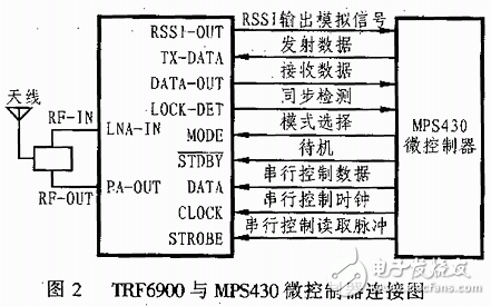
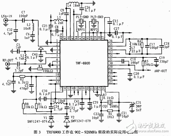
The typical application circuit of the TRF6900 RF transceiver chip is shown in Figure 2. Figure 3 shows the actual application circuit of the TRF6900 operating in the 902-928MHz band. In the connection diagram of the TRF6900 and the MPS430 microcontroller shown in FIG. 2, since the input signal line of the TRF 690 is connected to the programmable digital I/O terminal of the MPS 430, the indicated operation can be completed under the control of the MPS 430. Figure 3 shows the actual application circuit and component parameters of the TRF6900 operating in the 902-928MHz band.
The present invention provides a method for controlling the temperature of a flue-cured electronic cigarette and a flue-cured electronic cigarette. The flue-cured electronic cigarette includes an N-section heating body, where N is an integer greater than 1, and the heating body is used for heating tobacco. The method for controlling the temperature of the flue-cured electronic cigarette includes: the flue-cured electronic cigarette heats the i-th heating body, and i is an integer greater than 0 and less than N; after the first preset time, the flue-cured electronic cigarette pairs the i+ The first stage heating body is heated; after the second preset time, the flue-cured electronic cigarette stops heating the i-th stage heating body, and continues to heat the i+1th stage heating body. The technical solution solves the problem of unbalanced smoke output of flue-cured electronic cigarettes during multi-stage heating.The present invention provides a method for controlling the temperature of a flue-cured electronic cigarette and a flue-cured electronic cigarette. The flue-cured electronic cigarette includes an N-section heating body, where N is an integer greater than 1, and the heating body is used for heating tobacco. The method for controlling the temperature of the flue-cured electronic cigarette includes: the flue-cured electronic cigarette heats the i-th heating body, and i is an integer greater than 0 and less than N; after the first preset time, the flue-cured electronic cigarette pairs the i+ The first stage heating body is heated; after the second preset time, the flue-cured electronic cigarette stops heating the i-th stage heating body, and continues to heat the i+1th stage heating body. The technical solution solves the problem of unbalanced smoke output of flue-cured electronic cigarettes during multi-stage heating.
E-Cigarette Starter Kits,small e cigarette starter kit,mini e cigarette starter kit,e cig starter kit near me,cheapest e cigarette starter kit, e cigarette starter kits,electronic cigarette starter kits
Suizhou simi intelligent technology development co., LTD , https://www.msmvape.com