This paper introduces the current development of tunnel lighting control systems and lighting sources, and addresses the problems of current tunnel lighting control systems. An intelligent lighting control system was designed. The system makes full use of electronic technology and communication technology to achieve effective control and management of tunnel lighting fixtures. This paper analyzes and compares the characteristics of various tunnel lighting sources, determines the LED as the tunnel lighting fixture, and performs stepless control of the LED tunnel light according to the change of the traffic flow jI{= and the brightness outside the tunnel, so that the illumination of each section in the tunnel is smooth. In order to meet the human eye's adaptation curve, and use the bus communication mechanism to achieve the transmission of tunnel data.
Tunnel lighting center controller hardware design
The task of hardware design is to design the circuit schematic of the system based on the selected microprocessor chip and other components according to the design requirements of the system, including structural design and printed board design. Test after the design is completed to correct the unreasonable parts, and finally determine the hardware design and complete the printed circuit board. The central controller circuit mainly includes the following parts: (1) The core part of the circuit: ARM microprocessor, reset circuit, crystal oscillator circuit and power supply circuit. (2) JTAG circuit: realize program download and online debugging. (3) Peripheral circuit: CAN bus communication circuit, USB interface, storage circuit, LCD liquid crystal display, keyboard circuit, serial communication circuit.
Core circuit design
The microprocessor pin diagram of the central controller is shown in Figure 3.2. It mainly includes the network label of each interface used in the chip and the connection with the peripheral circuit.
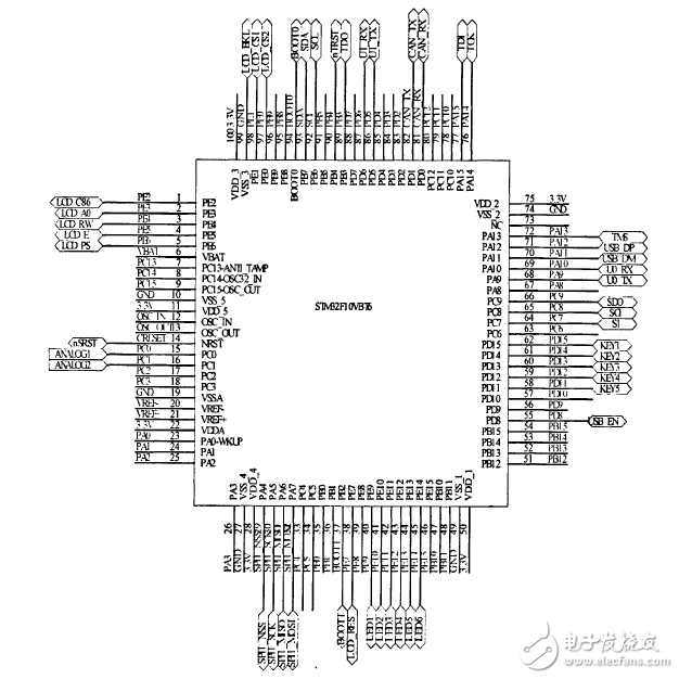
Figure 3.2 STM32F103VBT6 pin diagram
Power circuit design
The power supply circuit is shown in Figure 3.3.
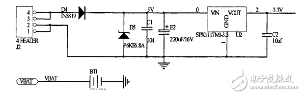
Figure 3.3 central controller power circuit
The operating voltage of the STM32 is 2.0V. 3.6V, the required 1.8V power supply is provided by a built-in voltage regulator. When the main power supply is powered down, power is supplied to the real-time clock (RTC) and backup registers via the VBAT pin. The 5v power supply is connected to the circuit through the J2 port, and the power supply is regulated to 3.3V through SPXlll7M3.3.3. VDDA and VSSA must be tied to VDD and VSS, respectively, to reduce noise and error rates. SPXI 1l 7M3.3.3 output current up to 800mA, the output voltage accuracy is between plus and minus one percent, with current limit and thermal protection. P6KE6.8A is a transient suppression diode that effectively protects precision components in electronic circuits from various surge pulses. The power supply is not only the power supply of the core circuit, but also responsible for supplying power to other peripheral circuits. The capacitance between the power supply and the ground is used for decoupling, which improves the anti-interference of the system.
Reset circuit design
The STM32F103VBT6 supports three reset modes, system reset, power-on reset, and backup area reset. In addition to the reset flag bits in the RCC CSR register of the clock control register and the registers in the backup area, a system reset will reset all registers to their reset states. The external reset circuit is shown in Figure 3.4.
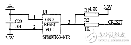
Figure 3-4 Center Controller Reset Circuit
SP809EK. 3.1/TR is a single function reset monitoring device. When the system is powered up or the power supply voltage drops to the threshold voltage, the SP809 reset signal RESET will generate a 140ms reset pulse to ensure a reliable and effective reset of the system. Its output is typically pulled up low, so add a pull-up resistor Rl between RESET- and "supply voltage. This circuit is an external reset, CRESET is connected to the NRST pin of lJSTM32F103VBT6. Low level. effective.
  
ZGAR AZ Vape Pods 5.0
ZGAR electronic cigarette uses high-tech R&D, food grade disposable pod device and high-quality raw material. All package designs are Original IP. Our designer team is from Hong Kong. We have very high requirements for product quality, flavors taste and packaging design. The E-liquid is imported, materials are food grade, and assembly plant is medical-grade dust-free workshops.
From production to packaging, the whole system of tracking, efficient and orderly process, achieving daily efficient output. WEIKA pays attention to the details of each process control. The first class dust-free production workshop has passed the GMP food and drug production standard certification, ensuring quality and safety. We choose the products with a traceability system, which can not only effectively track and trace all kinds of data, but also ensure good product quality.
We offer best price, high quality Pods, Pods Touch Screen, Empty Pod System, Pod Vape, Disposable Pod device, E-cigar, Vape Pods to all over the world.
Much Better Vaping Experience!


Pods, Vape Pods, Empty Pod System Vape,Disposable Pod Vape Systems
ZGAR INTERNATIONAL TRADING CO., LTD. , https://www.oemvape-pen.com