Linear optocoupler is an optocoupler used for analog signal isolation. Just like ordinary optocoupler, the linear optocoupler actually isolates the current. The linear optocoupler can protect the test object and the test circuit, and reduce the impact of environmental interference on the test circuit.
The isolation principle of the linear optocoupler is not different from the ordinary optocoupler. It only slightly changes the single-shot and single-receive mode of the common optocoupler, and adds an optical receiving circuit for feedback for feedback. In this way, although the two light receiving circuits are all non-linear, the nonlinear characteristics of the two light receiving circuits are the same. In this way, the non-linearity of the through path can be offset by the nonlinearity of the feedback path, so as to achieve the purpose of linear isolation.
Linear optocoupler detection circuit in the application circuitIn a follow-up detection system, it is necessary to monitor the parameters of each circuit board in the system with a test board to give fault indications to the circuit boards that are not working properly, and use the single-chip microcomputer to process the test results. Because the actual work environment is rather poor, in order to prevent the interference signal from the acquisition channel into the detection board and ensure the normal operation of the single-chip microcomputer system, the author uses an optocoupler to achieve signal transmission. Since the light-emitting diode of the optocoupler is a current-driven device, it should be transmitted in the form of a current loop, and the current loop is a low-impedance circuit, which is less sensitive to noise, and thus improves the anti-interference ability of the circuit. Sometimes interference noise has a large voltage amplitude, but its energy is small, so it can only form a weak current, and the light-emitting diode of the input part of the optocoupler works in the current state, only when a certain intensity of current is passed. Glowing, therefore, even if there is a high voltage amplitude disturbance, it will be suppressed due to the current that it forms.
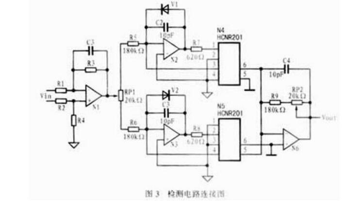
In an acquisition channel of an actual detection circuit, if a set of differential input signals needs to be detected, the circuit may be connected as shown in FIG. 3 . In the figure, the input differential signal can be output as a one-side signal through the amplifier N1. Due to the effect of diodes V1 and V2, when the input signal is positive, V2 is on, V1 is off, amplifier N2 is in an open-loop state, optocoupler N5 is operating, and N4 is off; when the input signal is negative, the opposite is true. When the photodiodes at the 3rd and 4th ends of the HCNR201 receive light, their output signals will be fed back to the input of the amplifier to increase the linearity of the optocoupler and reduce drift. The signals output by the 5th and 6th outputs are amplified by the op amp. Potentiometer RP1's role is to adjust the amplifier input bias current size. Capacitors C2 and C3 are feedback capacitors and can be used to increase the stability of the circuit, eliminate self-oscillation, filter out the glitch signal in the circuit, and reduce the output noise of the circuit. The capacitance can be selected based on the frequency characteristics of the circuit. The function of the amplifier N6 is to convert the current signal output by the optocoupler into a voltage signal for use by the subsequent circuit, and to enhance the load driving capability and reduce the output impedance. Adjust the value of resistor RP2 to adjust the gain of the channel.
Linear optocoupler isolation detection voltage circuitThe TIL300 is an isolated feedback photodiode and an output photodiode configured by an infrared LED bifurcate configuration. The device uses special manufacturing techniques to compensate for the non-linearity of the LED time and temperature characteristics, making the output signal linearly proportional to the emitted servo flux.
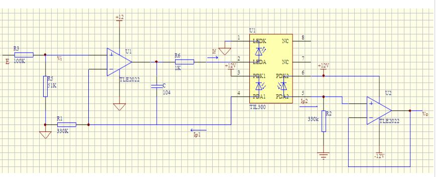
Capacitor C prevents the circuit from oscillating. The internal DO of the TIL300 is a light emitting diode, and its operating current If may be 10 mA. D1 and D2 are photodiodes. They are excited by DO to generate currents IP1 and Ip2, respectively, whose size is related to If:
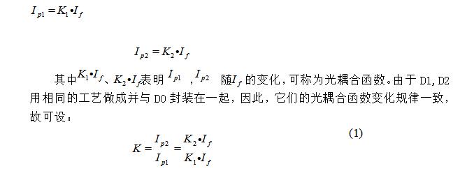
In fact, K can be regarded as a constant. The value of K is the electrical parameter of TIL300. The typical value is 1. The parameter value ranges from 0.75 to 1.25.
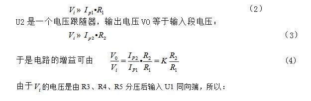
U1 constitutes a negative feedback amplifier. The voltages at the non-inverting input and the inverting input should be approximately equal, satisfying:
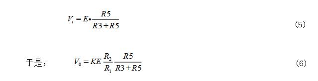
It can be seen that the output V% is linear with E.
analysis:
1. The typical value of K is 1.
2. Because the input may be AC ​​voltage of about 220V, it may be lower or higher AC voltage, so it involves transformer and rectifier circuit. Because the company has 220V AC output 12V transformer rectifier circuit module, No transformer rectifier circuit is given.
3, this circuit is also suitable for DC high voltage circuit, when E is DC high voltage, you need to adjust the value of R2, R1, at the output can be suitable for microcontroller detection voltage.
4. The output VO can be sent to the SCM for detection and processing. Each AC high voltage corresponds to an E value, and each E value corresponds to an output voltage VO. By  The proportional relationship between the output voltage of the entire circuit and the input current can be achieved by adjusting the resistors R1, R2, R3, and R5.
According to the technical description of the linear optocoupler, when the transmitting end and the two receiving ends are used in a certain range, the circuit will configure the relevant circuits on the D0, D1, and D2 ends of the linear optical coupler.
Good linearity,
Other linear optocoupler chip introduction:
HCNR200/201 is a cost-effective analog linear optocoupler introduced by Agilent in the United States. It has the advantages of low cost, high linearity, high stability, wide bandwidth, and flexible design. It can work in unipolar/bipolar Under the conditions of DC/AC, in-phase/inverting, etc., a variety of opto-isolated conversion circuits can be realized by externally connecting different discrete devices.
Its main features are as follows:
Non-linearity: 0.01%
K3 (Ipd2/Ipd1) transfer gain
HCNR200: (100 persons 15)%
HCNR201: (100 soil 5)%
Pressure resistance: AC 800V; DC 1000V
Gain temperature coefficient: -65ppm/"C
Bandwidth: "IMHz
8-pin DIP and SMD two packages
The main scope of application of HCNR200/201 includes:
Low-cost analog signal isolation;
Communication: Modem, PBX
Industrial process control
Thermocouple Isolation: 4-20mA galvanic isolation
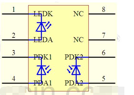
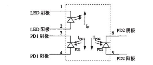
The HCNR200/201 includes a high performance light emitting diode (LED in the figure) and two very similar photodiodes (PD1 and PD2 in the figure). When the current If flows through the LED. The light it emits induces photocurrents Ipd1 and Ipd2 proportional to the luminous intensity of the LED in PD1 and PD2. Since the characteristics of PD1 and PD2 are very similar, the accuracy of the mounting position and the advanced flip-flop design of the component ensure the high linearity and gain stability of the component.
Rubber Wiring Harness,Rubber Flex Cable,Tough Rubber Sheathed Cable,rubber flexible cable
Dong guan Sum Wai Electronic Co,. Ltd. , https://www.sw-cables.com