Simple Network Management Protocol (SNMP) is a set of network management protocols defined by the Internet Engineering Task Force (IETF). The protocol is based on the Simple Gateway Monitor Protocol (SGMP). With SNMP, a management station can remotely manage all network devices that support this protocol, including monitoring network status, modifying network device configuration, and receiving network event alerts. Although SNMP was originally developed for IP-based network management, it was successfully used as an industry standard for telephone network management.
A complete SNMP system mainly includes Management Information Base (MIB), Management Information Structure (SMI) and SNMP message protocol.
(1) Management Information Base MIB: Any managed resource is represented as an object called a managed object. A MIB is a collection of managed objects. It defines a set of properties of the managed object: the name of the object, the access rights of the object, and the data type of the object. Each SNMP device (Agent) has its own MIB. The MIB can also be seen as a communication bridge between the NMS (Network Management System) and the Agent. The relationship between them is shown in Figure 1.
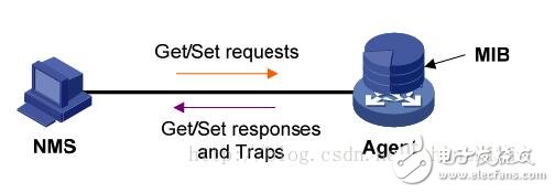
Figure 1 Relationship between NMS Agent and MIB
The names used in the variables in the MIB file are taken from the ISO and ITU-managed object identifier (object idenTIfier) ​​namespace. It is a hierarchical tree structure. As shown in Figure 2, the first level has three nodes: ccitt, iso, iso-ccitt. The low-level object IDs are assigned by the relevant organizations. The identifier of a particular object can be obtained from the path from the root to the object. Generally, the network device takes the object content under the iso node. For example, the MIB variable named ipInReceives under the namespace ip node is assigned a numeric value of 3, so the name of the variable is:
iso.org.dod.internet.mgmt.mib.ip.ipInReceives
The corresponding number representation (object identifier OID, uniquely identifying a MIB object) is:
1.3.6.1.2.1.4.3
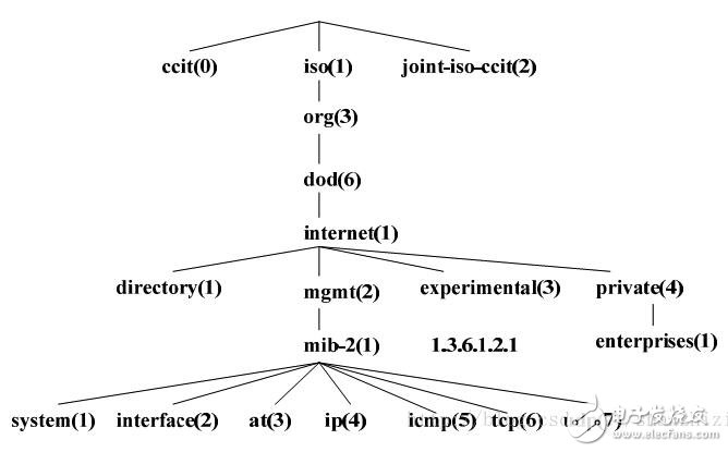
Figure 2 MIB tree structure
When the network management protocol uses MIB variables in the message, each variable name is followed by a suffix as an instance of the variable. The example number of ipInReceives is expressed as: 1.3.6.1.2.1.4.3.0.
It should be noted that some of the OIDs of the management objects in the MIB need to be dynamically determined, such as the IP routing table. To indicate the next hop of the address 202.120.86.71, we can refer to such an instance:
Iso.org.dod.internet.mgmt.mib.ip. ipRouteTable.ipRouteEntry.ipRouteNextHop.202.120.86.71, the corresponding number is: 1.3.6.1.2.1.4.21.1.7.202.120.86.71
For such an instance of the dynamic object identifier, since it cannot be converted to a pre-specified Readkey name, it conflicts with the product architecture of the flying neighbor (need to dynamically generate a variable Readkey), and no support is considered.
(2) Management Information Structure (SMI)
SMI defines the organization, composition, and identity of the information used by the SNMP framework. It also lays the foundation for describing MIB objects and describing how protocols exchange information.
The data type defined by SMI:
â—† Simple type (simple)
Integer: integer is a signed integer of -2,147,483,648~2,147,483,647
Octet string: The string is an ordered sequence of 0~65535 bytes.
OBJECT IDENTIFIER: from the set of object identifiers assigned according to ASN.1 rules
â—† Simple structure type (simple-constructed)
SEQUENCE is used for the list. This data type is similar to "structure" in most programming languages. A SEQUENCE consists of 0 or more elements, each of which is another ASN.1 data type
SEQUENCE OF type is used for forms. This data type is similar to "array" in most programming languages. A table consists of zero or more elements, each of which is another ASN.1 data type.
â—† Application type (applicaTIon-wide)
IpAddress: IP address in network order. Because it is a 32-bit value, it is defined as 4 bytes;
Counter: The counter is a non-negative integer that increments to the maximum value and then returns to zero. The counter defined in SNMPv1 is 32-bit, that is, the maximum value is 4,294,967,295;
Gauge : is also a non-negative integer, which can be incremented or decremented, but remains at the maximum when it reaches the maximum value, the maximum value is 232-1;
TIme ticks: is a unit of time indicating the time in units of 0.01 seconds;
SNMP packet
The SNMP message structure is as follows: (before encoding)
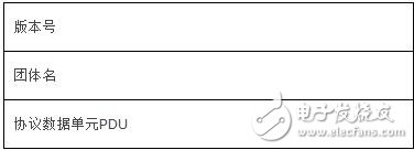
There are 5 kinds of messages in SNMP, so there are 5 PDUs. The seventh point will introduce the five protocol data units of SNMP in detail.
1. Five protocol data units of SNMP
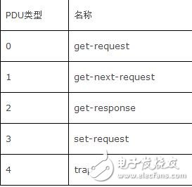
SNMP specifies five protocol data unit PDUs (also known as SNMP messages) for the exchange between the management process and the agent.
Get-request operation: Extract one or more parameter values ​​from the agent process.
Get-next-request operation: Extract the next parameter value from the agent process immediately following the current parameter value.
Set-request operation: Set one or more parameter values ​​of the agent process.
Get-response operation: One or more parameter values ​​returned. This operation is issued by the agent process, which is the response operation of the first three operations. Trap operation: A message sent by the proxy process to notify the management process that something has happened.
The first three operations are issued by the management process to the agent process. The latter two operations are sent to the management process by the agent process. For the sake of simplicity, the first three operations are called get, get-next, and set operations. Figure 1 depicts the five packet operations of SNMP. Please note that on the agent process side, the well-known port 161 receives the get or set message, and the management process end uses the well-known port 162 to receive the trap message.
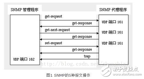
Figure 2 shows the SNMP message format of five operations encapsulated into UDP datagrams. It can be seen that an SNMP message consists of three parts: a common SNMP header, a get/set header, a trap header, and a variable binding.
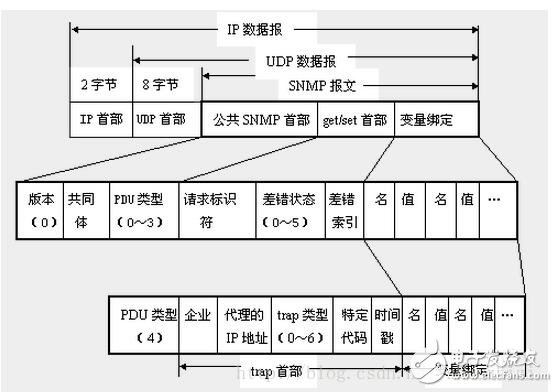
(1) Public SNMP header
A total of three fields:
ï¬ version
The version number is written minus 1 for the version field and 0 for SNMP (ie SNMPV1).
ï¬ Community
The community is a string, as the plaintext password between the management process and the agent process, commonly used is the six characters "public".
ï¬ PDU type
According to the type of the PDU, a number from 0 to 4 is filled in, and the corresponding relationship is as shown in Table 2.
Table 2 PDU types
(2) get/set header
ï¬ request identifier (request ID)
This is an integer value set by the management process. The proxy process also returns this request identifier when sending a get-response message. The management process can send get messages to many agents at the same time. These messages are transmitted by UDP, and may be sent first. Setting the request identifier enables the management process to identify which request message the returned response message is for.
ï¬ error status
Fill in a number from 0 to 5 when answering by the agent process, as described in Table 3.
Table 3 Error status description
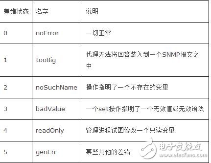
ï¬ error index
When an error of noSuchName, badValue, or readOnly occurs, an integer set by the proxy process when answering, indicating the offset of the variable with the error in the variable list.
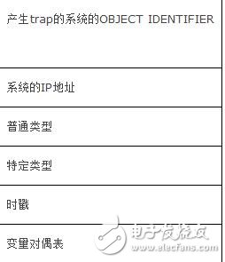
(3) trap header
ï¬ Enterprise (enterprise)
The object identifier of the network device that filled in the trap message. This object identifier is definitely on a subtree below the enterprise node {1.3.6.1.4.1} on the object naming tree of Figure 3.
ï¬ trap type
The official name of this field is generic-trap, which is divided into seven categories in Table 4.
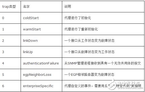
When using the above types 2, 3, 5, the first variable in the variable part after the message shall identify the interface of the response.
ï¬ specific code (specific-code)
Indicates the agent's custom time (if the trap type is 6), otherwise 0.
ï¬ Timestamp
Indicates the time elapsed since the event that the agent process was initialized to the trap report, in 10ms. For example, a timestamp of 1908 indicates that this time occurred 1908 ms after the proxy initialization.
(4) variable-bindings
Indicates the name and corresponding value of one or more variables. In a get or get-next message, the value of the variable should be ignored.
Representation of management variables
The management variable represents the value of the managed object type at a certain time (or an instance of the type), and SNMP manages the variable as the operation object.
The representation of the managed variable is specified as: xy, where x is the object identifer of the managed object. y is a set of numbers that can uniquely determine the value of the object type. It is 0 in the non-phenotype variable. In the phenotype variable, it is the index of the table, such as the interface number in the interface table, or the destination network address in the routing table. Wait. For example, the management object of ipAdEntNetMask is defined in the MIB file, and its object identifier is 1.3.6.1.1.5.6.1.3. It is an item in the routing table. An instance of it is the subnet mask of a row in the routing table. Code, if the index of this line, the destination network address is 129.102.1.0. Then the variable name is: 1.3.6.1.1.5.6.1.3.129.102.1.0. In the following description, for convenience, a set of numbers that uniquely determine a management variable, that is, y in xy is referred to as an instance.
SNMP running processThe AGENT residing on the managed device accepts the serialized message from the network management station from the UDP port 161, and obtains the corresponding node of the management variable in the MIB tree through decoding, community name verification, and analysis, and is managed from the corresponding module. The value of the variable is then formed into a response message, and the code is sent back to the network management station. After the network management station receives the response message, it performs the same processing and finally displays the result.
The following takes the action taken by the Agent after receiving the message according to RFC1157:
First, the packet generated by the internal data structure is decoded and decoded according to the basic encoding rule of ASN.1. If an error occurs in the process, the packet is discarded, and the packet is discarded without further processing.
Step 2: The version number in the packet is removed. If the SNMP version supported by the agent is inconsistent, the packet is discarded and no further processing is performed. Currently, North Research's data communication products only support SNMP version 1.
Step 3: Take out the community name in the message. The community name is filled in by the requesting network management station. If the name of the community is not consistent with the device, the packet is discarded, and no further processing is performed. A trap message is generated. SNMPv1 only provides weaker security measures, and this feature will be greatly enhanced in version 3.
Step 4: Propose the protocol data unit PDU from the authenticated ASN.1 object. If it fails, discard the message and do not process it. Otherwise, the PDU is processed, and a message is generated. The destination address of the packet should be the same as the source address of the received packet.
According to different PDUs, SNMP protocol entities will do different processing:
1.1, GetRequest PDU
The first case: If the variable name in the PDU does not exist in the locally maintained MIB tree, the protocol entity that receives the PDU will send a GetResponse message to the sender, where the PDU is only slightly different from the source PDU: ERROR-STATUS is set to noSuchName, and the location of the variable in the variable LIST is indicated in ERROR-INDEX.
The second case: If the length of the response packet generated by the local protocol entity is greater than the local length limit, a GetResponse message will be sent to the sender of the PDU. The PDU is set to tooBig except ERROR-STATUS, and ERROR-INDEX is set to Other than 0, it is the same as the source PDU.
The third case: If the local protocol entity cannot generate the correct response message for other reasons, it will send a GetResponse message to the sender of the PDU. The PDU is set to genErr except ERROR-STATUS, and ERROR-INDEX is set to the error variable. The position in the variable LIST is the same as the source PDU.
The fourth situation: if none of the above occurs, the local protocol entity sends a GetResponse message to the sender of the PDU, the PDU will contain the dual table of the variable name and the corresponding value, ERROR-STATUS is noError, ERROR- INDEX is 0, and the value of the request-id field should be the same as the request-id of the received PDU.
1.2, GetNextRequest PDU
The most important function of the GetNextRequest PDU is the traversal of the table. This operation is supported by the representation of the managed variables mentioned above, so that a set of related variables can be accessed as if they were in a table.
The following is an example to explain the process of table traversal:
The managed device maintains the following routing table:
Destination NextHop Metric
10.0.0.99 89.1.1.42 5
9.1.2.3 99.0.0.3 3
10.0.0.51 89.1.1.42 5
Suppose the network management station wants to obtain information about this routing table. The index of the table is the destination network address.
The network management station sends a GetNextRequest PDU to the managed device, where the managed object is identified as follows
GetNextRequest ( ipRouteDest, ipRouteNextHop, ipRouteMetric1 )
The SNMP agent responds with the following GetResponse PDU:
GetResponse (( ipRouteDest.9.1.2.3 = "9.1.2.3" ),
( ipRouteNextHop.9.1.2.3 = "99.0.0.3" ),
( ipRouteMetric1.9.1.2.3 = 3 ))
The network management station continues:
GetNextRequest ( ipRouteDest.9.1.2.3,
ipRouteNextHop.9.1.2.3,
ipRouteMetric1.9.1.2.3 )
Agent response:
GetResponse (( ipRouteDest.10.0.0.51 = "10.0.0.51" ),
( ipRouteNextHop.10.0.0.51 = "89.1.1.42" ),
( ipRouteMetric1.10.0.0.51 = 5 ))
It is worth noting that the agent must be able to determine the name of the next managed variable to ensure that all variables can be fetched and only fetched once.
The network management station continues:
GetNextRequest ( ipRouteDest.10.0.0.51,
ipRouteNextHop.10.0.0.51,
ipRouteMetric1.10.0.0.51 )
Agent response:
GetResponse (( ipRouteDest.10.0.0.99 = "10.0.0.99" ),
( ipRouteNextHop.10.0.0.99 = "89.1.1.42" ),
( ipRouteMetric1.10.0.0.99 = 5 ))
Network management station continues
GetNextRequest ( ipRouteDest.10.0.0.99,
ipRouteNextHop.10.0.0.99,
ipRouteMetric1.10.0.0.99 )
At this time, because all the rows in the routing table are taken, the agent returns the direct successor of the post-order traversal of the management object in the MIB tree by returning the next dictionary of the routing table object. This should be nettoMediaIndex, the OBJECT IDENTIFIER of the managed object. This response informs the network management station that the traversal of the table has been completed.
1.3, GetResponse PDU
The GetResponse PDU is generated by the protocol entity only when it receives the getRequest GetNextRequest SetRequest. After receiving the PDU, the network management station should display the result.
1.4, SetRequest PDU
The SetRequest PDU is the same as GetRequest except for the PDU type identifier. When the managed variable needs to be written, the protocol entity on the network management station side will generate the PDU.
The response to SetRequest will be handled separately according to the following conditions:
If the request is for a read-only variable, the protocol entity that receives the PDU generates a GetReponse message, and sets the error status to noSuchName. The value of the error index is the location of the error variable in the variable list.
If the value of the variable in the PDU received by the protocol entity on the managed device does not match the type and length, the protocol entity that received the PDU generates a GetReponse message and sets the error status to badValue, error index. The value is the location of the error variable in the variable list.
If the length of the GetReponse packet exceeds the local limit, the protocol entity that receives the PDU generates a GetReponse packet, and sets the error status to tooBig. The value of the error index is 0.
If the SET fails due to other reasons, the protocol entity that receives the PDU generates a GetReponse message, and sets the error status to genErr. The value of the error index is the location of the error variable in the variable list.
If any of the above conditions are not met, the agent will set the management variable to the corresponding value in the received PDU, which can often change the operational state of the managed device. At the same time, a GetResponse PDU is generated, in which error status is set to noError and the value of error index is 0.
1.5, Trap PDU
The Trap PDU has the following form:
A trap is a message that the managed device sends to the NMS station when it encounters an emergency. After receiving the trap PDU, the network management station shall display the contents of the variable dual table. Some commonly used trap types include cold and hot start, and link status changes.
Zinc Die-casting Alloy Ingot,Zinc Die-casting Alloy Ingot,ZAMAK 3 Ingot,ZAMAK3 Alloy Ingot
Shaoxing Tianlong Tin Materials Co.,Ltd. , https://www.tianlongspray.com