First, the common fault diagnosis and treatment of single-phase motor
1. The power supply voltage is normal, the motor does not start after power-on.
1) The power wiring is open (the motor is completely silent). There should be no voltage across the measurement terminals.
2) The main winding or auxiliary winding is open. The method of measuring the DC resistance can be used to determine whether or not the circuit is open.
3) The centrifugal switch contact is not closed, so that the auxiliary winding can not be energized. The connection point of the main winding and the auxiliary winding is disconnected, and then determined by measuring the DC resistance, or by the method of the second part.
4) The start capacitor wiring is open or internally open. The search method is the same as item 3) above.
5) Open/drop the shaded pole motor (short-circuit ring). For the short-circuit ring to be set externally, it can be found by observation, otherwise it can be determined by the method of the second part.
6) For the series-excited motor, the brush cannot be connected to the commutator due to the short brush or jam, or the brush lead is disconnected, or the armature winding or the field winding is open internally.
2. The power supply voltage is normal. After the power is turned on, the motor rotates at a low speed. There is a “beep†sound and vibration, and the current does not drop.
1) The load is too heavy.
2) The motor stator and rotor are rubbed. An abnormal rubbing sound will be emitted.
3) The bearing is stuck due to poor bearing assembly, grease consolidation in the bearing, bearing roller bracket or roller damage.
4) For series-excited motors, short-circuit between commutating segments or internal short-circuit of armature windings, or excessive deviation of the brush from the centerline (motors that can move the brush).
3. After the power is turned on, the power fuse is blown quickly
1) A severe short circuit between winding turns or ground. Measure the DC resistance. If the value is much smaller than the normal value, it is the short circuit between the windings. The severe short circuit to the ground can be measured by the insulation resistance meter or the high resistance file of the multimeter (for example, R×1k). The current will be greater than the rated value.
2) The motor leads the phase line to ground. The inspection method is the same as the fault item 1).
3) The capacitor is shorted. This is determined by measuring the DC resistance between the ends of the start winding circuit (including the capacitor and the start winding, excluding the centrifugal switch) with a lower resistance of the multimeter (eg, R x 1).
4) The centrifugal switch is shorted to ground. The inspection method is the same as item 1).
5) The load is too heavy. The sound will be abnormal and the current will be greater than the rated value.
4. After the motor starts, the speed is lower than the normal value.
1) The main winding has a short circuit to the ground or to ground. The inspection method is the same as item 1 in item 3.
2) There is a coil reverse connection fault in the main winding. The sound will be abnormal and the current will be greater than the rated value.
3) The centrifugal switch is not disconnected, so that the auxiliary winding cannot be disconnected from the power supply. The current will be greater than the rated value.
4) Heavy load or bearing damage. The sound will be abnormal and the current will be greater than the rated value.
5) For series-excited motors, short-circuit between commutating segments or internal short-circuit of armature windings, or poor contact between brushes and commutators.
5. When the motor is running, it will heat up very quickly
1) The winding (including the main winding and the auxiliary winding) is short-circuited between turns or ground. The inspection method is the same as item 1 in item 3.
2) There is a short circuit fault between the main winding and the auxiliary winding (other than the end connection point). The current will be greater than the rated value.
3) After starting, the centrifugal switch is not disconnected, so that the auxiliary winding cannot be disconnected from the power supply. The current will be greater than the rated value.
4) For single-phase split-phase motors other than single-phase capacitor motors with main windings running at the main or only the main windings, except for the single-capacity motor that starts and operates with the same capacitance of the two windings, the main winding and the auxiliary winding are connected to each other incorrectly. The current will be much larger than the rated value.
5) The working capacitor is damaged or the wrong capacity is used.
6) Fixed, rotor core rubbing or bearing damage. The sound will be abnormal and the current will be greater than the rated value.
7) The load is heavy. The current will be greater than the rated value.
8) For series-excited motors, short-circuit between commutating segments or internal short-circuit of armature windings, or poor contact between brush and commutator.
6. Motor running noise and vibration are large
The noise and vibration (especially vibration) of a single-phase motor is relatively large compared to a three-phase asynchronous motor of the same capacity or the same frame number. This is because its stator rotating magnetic field is not a regular circular shape, so the torque will not be equal at all times, that is, there will be fluctuations in size within one circumference, resulting in radial vibration of the rotor.
Common causes of loud noise and vibration are as follows:
1) Poor immersion paint, causing looseness between the core sheets, resulting in higher frequency electromagnetic noise.
2) The centrifugal switch is damaged.
3) Bearing damage or excessive axial turbulence.
4) The air gap is uneven or axially misaligned between the stator and the rotor.
5) There is foreign matter inside the motor.
6) For series-excited motors, short circuit between commutating segments or internal short circuit of armature windings, or poor contact between brush and commutator (mica between commutator segments is higher than commutator segments or commutator segments, or brush is too hard , too much pressure, etc.).
Second, the method is determined that the auxiliary winding is broken or the capacitor is damaged, and the motor is not started.
After the single-phase capacitor is started and the motor is turned on, it does not start and there is almost no sound. If it is measured with an ammeter, there is a certain current. At this time, apply the multimeter resistance (R × 1) file to check whether the auxiliary winding circuit is unreachable. The reason for the failure is that the winding or wiring is broken, or the capacitor is broken.
In the absence of a multimeter, the following simple method can be used to check whether the auxiliary winding or capacitor has an open circuit fault.
In the case of power failure, short-circuit the two electrodes of the capacitor with a wire or other conductive device (such as a screwdriver) to discharge, to prevent the battery from being stored in the case of no damage to the capacitor, and to cause electric shock when the human body is in contact (if there is A strong discharge phenomenon can eliminate the problem of capacitor damage). After that, untie the connection between the capacitor and the motor and wrap it in an insulating material.
Remove the load of the motor (for example, remove the drive belt. For loads that require less starting torque, if it is difficult to remove the load, do not remove it), then energize the motor (pay attention to insulation work), by hand (or Tool) Twist the shaft in order to rotate it in one direction, as shown below. If the rotor of the motor rotates at this time, it automatically accelerates until it reaches the normal speed. After the power is turned off, the motor shaft extension is rotated in the opposite direction. If the motor rotor is also rotated in the same direction, it is basically determined that the auxiliary winding or the capacitor is not activated due to the open circuit. Then further check that there is an open circuit fault in the capacitor or the winding (including the wiring).

Third, the simple judgment method of the capacitor is good or bad
When inspecting a used capacitor, first connect the two poles with a wire (or other metal) to avoid electric shock damage to the tester due to the internal stored charge.
1. Check the quality of the capacitor with a multimeter
When you suspect that a capacitor is damaged or has a quality problem, you can use a pointer multimeter to make a rough decision. Please refer to the figure below.
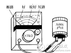
Set the multimeter to the R × 1k (or R × 100) block of the resistance bar. Use two test leads to contact the two electrodes of the capacitor under test. Watch the reaction of the hands and determine the quality status of the capacitor according to the reaction.
1) The pointer is quickly placed at zero (0Ω) or near zero, then slowly go back (to the side of ∞Ω), go somewhere and stop. It shows that the capacitor is basically intact, and the closer the return position is to the ∞Ω point, the better the quality, and the farther away, indicating more leakage.
This is because the principle of measuring the resistance of the multimeter is actually adding a fixed value of DC voltage to the conductor under test (provided by the battery installed in the table). At this time, there will be a corresponding current, which will be based on Ohm's law. This current is converted to a resistance value scale on the dial. For example, if the current is 0.03A at a voltage of 9V, the resistance of the conductor is 9V/0.03A=300Ω, and the mark at the 0.03A position on the dial is 300Ω.
For a good capacitor, when a DC voltage is applied to both ends, charging starts, the current will reach the maximum value instantaneously, and it is close to 0Ω for the resistance of the multimeter resistance file. As the charging process progresses, the current also flows. It will gradually decrease. Theoretically, the two plates of the capacitor should be completely insulated. Therefore, the final result of the above charging process should be that the current reaches zero, reflected on the resistance, and finally should return to the ∞Ω point. At the location (ie, where the current is equal to zero). But in fact, all the capacitor plates are not completely insulated, so there will be a small current under the applied voltage, which is called the "leakage current" of the capacitor. This means that the pointer cannot return completely to the ∞Ω point. the reason. The amount of leakage of the multimeter's hands indicates the magnitude of the leakage current. If the return is large, the leakage current is small. If the return is small, the leakage current is large. The leakage current should not be too large, otherwise it will cause some abnormal phenomena of the circuit. If it is serious, it will not work normally. When the leakage current is large, the capacitor will be much hotter than normal.
2) The pointer will not move after the zero position (0Ω) or near zero position, indicating that a short circuit fault has occurred between the two plates of the capacitor, and the capacitor can not be reused.
3) When the two electrodes of the test leads and the capacitor start to be turned on, the pointer does not move at all, indicating that the internal connection of the capacitor has been disconnected (generally occurring at the junction between the electrode and the plate), and naturally cannot be used any more.
2. Use the charging and discharging methods to judge whether the capacitor is good or bad.
When there is no multimeter at hand, the method of charging and discharging can be used to roughly check whether the capacitor is good or bad. The power supply used is generally DC (especially a polarized capacitor such as an electrolytic capacitor, and a DC power supply must be used). The voltage should not exceed the withstand voltage of the capacitor to be tested (marked on the capacitor). A dry battery of 3 to 6 V is commonly used. Or 24V, 48V electric bicycles and automotive batteries. For capacitors that are connected to the AC circuit during operation, AC power can also be used, but when the voltage is high, safety should be taken during operation. Wear insulated gloves or use insulated tools.
After the DC power is applied to both ends of the capacitor, wait a little while to disconnect the power. Then, use a length of wire, one end is connected to one pole of the capacitor, and the other end is connected to the other electrode of the capacitor, while watching whether there is a discharge spark between the electrode and the wire. As shown below.

If there is a large discharge spark and a squeaky discharge sound, the description is good, and the larger the spark capacity is also larger (for the same specification of the capacitor, when using the same power supply for charging); the discharge spark and the discharge sound are small , indicating that the quality is not very good; there is no discharge spark, the explanation is bad.
Battery Online Monitoring System
Multifunctional Battery,Read Data And Information Battery,Safety Monitoring System Battery,Custom Monitoring System Battery
Wolong Electric Group Zhejiang Dengta Power Source Co.,Ltd , https://www.wldtbattery.com