With the rapid development of the water treatment process, the control method is more and more complicated, and there will be more automatic control problems for the large ultrafiltration sewage treatment system. How to realize the efficient, stable, reliable and safe operation of the ultrafiltration sewage treatment system will become the focus of research on the large-scale development of large-scale ultrafiltration sewage treatment systems in the future. This paper takes the 600,000 tons/day ultrafiltration sewage treatment system of Beijing Xiaohongmen Wastewater Treatment Plant as the research object, and solves the problem of corridor competition during backwashing and air scrubbing, which not only ensures the safety of ultrafiltration membrane, but also realizes For the non-stability problem of the incoming water quantity, the adaptive step water intake control method is adopted to realize the concept of “on-demand controlâ€, that is, to control the processing capacity of the system according to the current actual amount of water to be processed. It ensures the continuous and stable operation of the whole ultrafiltration system; the water hammer problem has always been one of the problems that restrict the development of large-scale ultrafiltration control systems. This study has better reduced the use of variable frequency S-curve stop pump and PWM valve control technology. Water hammer impact. In order to achieve efficient water production, the queue scheduling algorithm can be used to solve the problem of corridor competition. The introduction of dual ring network technology (large ring + small ring) achieves the stability of the entire system.
2, ultrafiltration sewage treatment system
2.1 Principle of ultrafiltration sewage treatment system
Ultrafiltration wastewater treatment is a screening process related to membrane pore size. The pressure difference between the two sides of the membrane is used as the driving force. The ultrafiltration membrane is used as the filter medium. Under a certain pressure, when the raw liquid flows through the membrane surface, Many fine micropores densely coated on the surface of the ultrafiltration membrane allow only water and small molecules to pass through to become permeate, and substances in the original solution having a volume larger than the micropore of the membrane surface are trapped on the liquid inlet side of the membrane to become a concentrate. Thus, the purpose of purifying, separating and concentrating the raw liquid is achieved. The ultrafiltration sewage treatment system is to use a large-scale ultrafiltration membrane to filter the large amount of sewage and finally achieve the function of purification and screening, thereby realizing the effect of sewage treatment. The system studied in this paper uses a clear water source ultrafiltration membrane.
2.2 Overview of ultrafiltration wastewater treatment control
The ultrafiltration sewage treatment control system is a system that realizes automatic control and automatic production of ultrafiltration sewage treatment system by adopting automatic control technology. The control system uses Rockwell Automation PLC as the main controller, and the valve island is used as the remote I/O to control the corridor pneumatic valve in the system. The system is connected through the system network of “main ring + sub-ringâ€. communication.
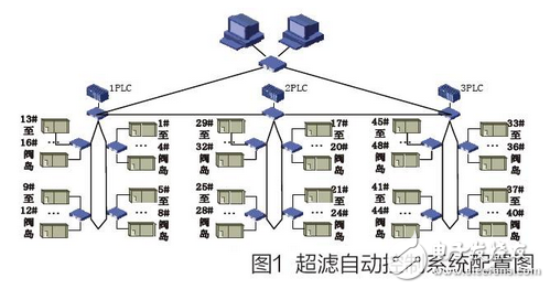
Figure 1 is a hardware configuration diagram of the system. The system consists of three main stations and 48 sub-stations, all of which have Ethernet communication functions and form a large ring network. There are 16 substations connected to each main station, and these 16 substations become a small ring network. For the convenience of subsequent description, we have named the three main stations and 48 sub-stations respectively. It is divided into No. 1 main station and 16 substations below. We call it the Ultrafiltration 1 series, and the 16 substations in it are corresponding to the No. 1 to No. 16 substations according to the corridor number. The No. 2 main station and the 16 substations below it are called the Ultrafiltration 2 series, and the substations are numbered 17 to 32. The No. 3 main station and the 16 substations below it are called the Ultrafiltration 3 series. Similarly, the substation No. 33 to No. 48 substations correspond to the ultrafiltration No. 33 to No. 48 corridor equipment.
Each substation has an Ethernet port, and the 16 substations of each series are geographically close, so the system uses four sets of valve island substations to share one switch. A fiber link is used between the switch and the switch. A twisted pair link is used between the valve terminal and the switch. The ultrafiltration system PC monitoring system is located in the large ring network to monitor the entire ultrafiltration system.
3. Ultrafiltration sewage treatment control system
The system will be divided into three parts: water control, water production and acid-base cleaning control, water hammer and other ancillary controls.
3.1 Inlet control
Influent control requires the injection of water from the collection basin into the ultrafiltration membrane. However, in the injection process, considering the pressure resistance of the ultrafiltration membrane, the ultrafiltration membrane should be filled with water at a constant pressure. As a container for buffering incoming water, the collecting basin has a certain capacity of water carrying capacity, but it cannot carry a large amount of unloaded, and can only change the small amount of water. Therefore, in the control, it is necessary to consider the impact of the change of the incoming water on the cistern. The ability to handle the amount of water in the ultrafiltration membrane should also be fully considered.
Each series of the system consists of 8 inlet pumps, which need to adopt constant pressure water inlet. The pressure setting is in one-to-one correspondence with the flow rate of the produced water. This parameter is determined by the performance of the Bishui source ultrafiltration membrane. The parameter comparison table can be queried according to the product specification. During normal operation, the level of the collection tank should be maintained within a safe liquid level. However, the amount of water in the pool is determined by the amount of people living in the daily life, and the amount of water is related to people's daily habits.
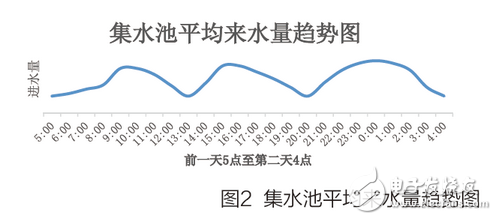
The 24-hour average water intake trend chart is shown in Figure 2. It can be seen from the figure that the water intake gradually increases around 7:00 in the morning and reaches the first peak when it reaches about eleven. This is due to the increase in water consumption in the morning. Normally, the water consumption peak is around 7:00 in the morning, and the delay of the pipe network causes the water intake to reach a peak at around 10:00. The same 13 points and the next day zero are the two water inflow peaks. The extension of the third peak period was due to people's lives during this period, such as the water consumption during the dinner time and the water used in the bath time.
For daily water peaks, we can adjust the processing parameters in real time in the water treatment inlet control section, but too frequent adjustment of the water treatment parameters will have a greater impact on the entire membrane system. First, too frequent adjustment of the water treatment parameters will cause frequent changes in the pressure of the ultrafiltration membrane, and there will be more spikes due to too frequent pressure changes. These pressure peaks are prone to pressure shock on the ultrafiltration membrane, which is not conducive to membrane life. Second, frequent adjustments to water treatment parameters can easily lead to frequent adjustments of other ancillary equipment, affecting the stability of the entire system, and also reducing the life of its ancillary equipment. However, it is easy to adjust the water treatment volume according to the amount of water to be used, which may easily cause the overflow of the water collection tank or the unsuccessful treatment. Therefore, in terms of water intake control, it is necessary to satisfy the adaptive water intake to control the influent water, and not to operate the water treatment amount parameter too frequently.
Based on the above problems, we propose a control method for adaptive step water inflow, which can not only adjust the water treatment parameters according to the change of the amount of water, but also does not adjust the water treatment parameters frequently. The amount of water automatically adjusts the amount of water produced, and finally realizes the water production function according to the amount of water that is adaptive.
We assume that the water flow at time t is Fi(t), the liquid level of the sump is L(t), S is the bottom area of ​​the sump, the membrane water volume Fo(t), ΔL_i(t) is the incoming water level. Increment, L_(t-1)(t) is the liquid level at t-1, and ΔL_o(t) is the increment of the operating level for the ultrafiltration system. Can know:
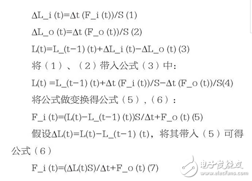
First, we can see from equation (4) that in order for L(t) to reach a relatively stable value, F_i(t) must be made close to F_o(t). But it is practically impossible to approach, and it cannot be approached in real time. Because if it is approached in real time, it will cause frequent changes in the water treatment parameters of the ultrafiltration system. Therefore, we convert it to formula (6). In order to make F_o(t) change infrequently, we temporarily set a fixed value for it. Thus, for a range of F_i(t), there will be a ΔL(t). The range corresponds to L_(t-1)(t), which is the value of the previous time. Using the idea of ​​recursion, it can be considered as a fixed value, so that the future water quantity range can be converted into a fixed treatment water quantity F_o ( t) and a range of liquid levels L(t).
According to the law of water inflow of the ultrafiltration system, through a number of experimental tests, we finally set a corresponding data set that is more suitable for the liquid level range and flow of the ultrafiltration system. The specific correspondence is shown in Table 1:
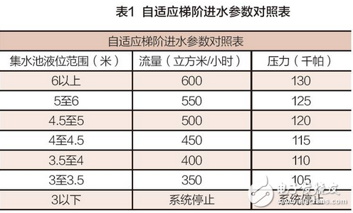
Table 1 is a comparison table of parameters of step adaptive liquid level and flow pressure in the system. The pressure here corresponds to the flow rate, and the pressure is obtained by comparing the parameters of the membrane. The liquid level and flow rate are obtained through rough calculations and experimental corrections. When the liquid level of the sump is more than 6 meters, there is a risk of overflow, and the system is running at full load at this time. When it is less than 3 meters, in order to prevent the lift pump from pumping, we will stop the system.
By controlling according to the parameters of Table 1, the system can better cope with the change of the amount of incoming water, and the system water treatment parameters will not change frequently.
3.2 Filtration of water production and acid and alkali cleaning control
Filtration of water production and acid-base cleaning control in ultrafiltration systems is one of the focuses of research on ultrafiltration control systems. The ultrafiltration filtration process is a multi-time operation of different events. This process consists of four stages: water production, water backwashing, gas water backwashing and emptying. Each stage of the same corridor is unique. The operation in the water production phase is directly linked to the production, and the other phases are only for the protection of the ultrafiltration membrane.
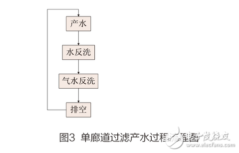
The flow chart of the filtration process of the single corridor is shown in Figure 3. It can be seen from the figure that the four stages involved in the ultrafiltration production process are sequentially executed in sequence, and then cycled again. In these four stages, only the water production and emptying are independent behaviors of a single corridor, and the equipment used in the water backwashing and gas water backwashing stages of a single corridor is the public equipment of the corridor, that is, the air scrubbing Presses, backwash pumps and other ancillary public equipment. Therefore, when performing water backwashing and gas water backwashing, there should be at most one corridor per time period and at most one corridor for the behavior of this stage. However, in actual operation, since multiple corridors are running in the normal filtration process, this will cause conflicts between water backwashing and gas-water backwashing between the corridor and the corridor. Water backwashing and gas water backwashing are generally referred to as backwashing. The phenomenon of conflicts in the backwashing stage of the filtration process of each corridor is called the corridor backwash competition, which is referred to as corridor competition.
If the treatment of the corridor competition is unreasonable in the process of filtering the produced water, it is easy to reduce the output of the ultrafiltration system, and it is even possible to reduce the life of the ultrafiltration membrane. Because when many corridors request backwashing at the same time, if you can't get backwashing in time and continue to work for a long time, it will have an impact on membrane life. However, if multiple corridors have backwash requests and are backwashing one corridor, while other corridors with backwash requests are waiting, the output of the ultrafiltration system will be reduced. And as the number of corridors increases, the competition for galleries becomes more intense. Therefore, solving the competition problem of the corridor is actually a timely (relative) response to the anti-washing request of the competition corridor, and it is necessary to handle the running state of the competition corridor.
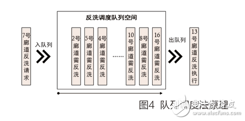
Here we use the queuing method to deal with corridor competition issues. The queuing method is a scheduling method that follows the principle of first in, first out. The specific principle is shown in Figure 4. Queue scheduling consists of three parts: the inbound queue, the outbound queue, and the scheduling queue space. The queue is a process of pushing the corridor with backwashing demand into the queue space according to the corridor backwash request. The out queue is the process of popping up the queues that need to be backwashed according to the current state of the backwashing equipment. The backwash scheduling queue space plays the role of a storage scheduling sequence, and it also has the function of optimizing and arranging sequences.
Here's how to put a corridor backwash request into the queue:
Check if there is a backwash request, if there is any progress, continue to query.
Check whether the queue space is empty. If it is empty and there is a corridor backwashing, push the backwash request into the queue scheduling space and proceed to the next step; if it is empty and there is no backwash corridor, respond directly to the gallery. The route is backwashed and returned to (1); if the queue space is not empty, the backwash request is directly pushed into the queue scheduling space and then proceeds to the next step.
Clear the backwash request for this corridor.
The above steps are queued for this, but it can be seen that the second step of the logic for the queue entry step is too confusing. For the PLC, it is too resource-intensive, so we optimize the above steps. The specific steps are as follows:
Check if there is a backwash request. If there is a next step, continue to query.
Check if there is a corridor that is backwashing. If there is no corridor cleaning, respond directly to the backwash request and return (1); otherwise proceed to the next step.
Push the backwash request of this corridor into the queue space and clear the backwash request for this corridor.
It can be seen that in the second step, the first query "whether there is a corridor is backwashing" can avoid querying the queue space here, and the efficiency of the queue entry is improved.
The outbound queue is actually a process of popping up the required backwashed corridors according to the order of the queue space. The specific steps of this process are as follows:
The query is whether the address space is empty. If yes, continue the query, otherwise the next step.
Check if there is a corridor that is backwashing. If yes, continue to return (1), otherwise the next step.
The nearby backwashing corridor for the pop-up queue space responds to the backwash of the corridor.
Confirm the pop-up corridor and make it clear that this corridor is occupied in the queue space.
The queue space sequence is rounded and returned (1).
The entire dequeuing process is described above, and the "nearby" of (3) refers to the nearest direction to and from the queue.
Through the description of each part of the scheduling queue, it can be seen that the queue scheduling has the following characteristics: (1) Timeliness. During the entire queue scheduling process, due to the separate way of the ingress and egress, the package becomes an egress pop-up queue on demand, and the portal is pushed into the queue according to the actual situation. (2) First in, first out. In the whole process of ultrafiltration production, the first-in-first-out method can ensure that the waiting time of the corridors that need to be backwashed is not too long, and finally the waiting time for each corridor to respond to backwashing is minimized, and it is guaranteed. The waiting time of each corridor has reached a balance, which enhances the fairness of the competition in the corridor.
Secondly, regarding the acid-base washing in ultrafiltration, it is carried out according to the requirements of the user. Here, there is randomness in time, so it will not be described.
3.3 Water hammer and other ancillary controls
Because the pump is turned on, the pump is stopped, and the switch valve is too fast, the speed of the water changes drastically, especially the water hammer caused by the sudden stop of the pump, which can damage the pipeline, the water pump, the valve, and cause the water pump to reverse and the pressure of the pipe network to decrease. The water hammer effect is extremely destructive: if the pressure is too high, it will cause the pipe to rupture. Conversely, if the pressure is too low, it will cause the pipe to collapse and damage the valve and the fixing member. In a very short time, the flow of water increases from zero to the rated flow. Since the fluid has kinetic energy and a certain degree of compressibility, a large change in flow rate in a very short period of time will cause an excessively high and low pressure on the pipeline. The pressure shock will force the wall of the pipe to generate noise, just like a hammer hitting a pipe, so it is called a water hammer.
Due to the large scale of the ultrafiltration system, the pipeline is thick and the water hammer is obvious. The water hammer position mainly exists in the lift pump outlet pipe, the backwash pipe, the ultrafiltration membrane inlet pipe and the ultrafiltration membrane outlet pipe of the system. For the installation positions of these pipes and equipment, it is known that the causes of water hammer are different in each position, as shown in Table 2:
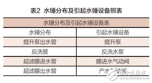
It can be seen from Table 2 that the equipment that causes the water hammer effect in the system is mainly divided into a water pump and a pneumatic valve. Therefore, if we cut or eliminate the water hammer, we may consider these two aspects.
Through observation and calculation of the site, we know that the water hammer mainly exists when the valve is closed and the pump is stopped, and it belongs to the direct water hammer. The direct water hammer has a relationship with the pump stop time and the valve closing speed. Therefore, to solve the direct water hammer, the pump should be stopped by the pump, and for the realization of the pneumatic valve closing, we use PWM control. The way to control the slow closing of the pneumatic valve.
In this system, the lift pump and backwash water pump are all variable frequency control, so we can achieve this by setting the stop time and parking mode of the inverter. And after many trials, the parking mode uses the S curve to stop the effect better. In terms of parking time, the test found that the system lift pump stop time is set to 25.3 seconds is the best, and the backwash pump stop time is set to 11.5 seconds is the best.
For the function of slowly closing the pneumatic valve, we use the PWM control method. In this system, the control of the pneumatic valve uses a valve island. The valve terminal control is to open or close the pneumatic valve by directly controlling the on and off of the cylinder through the programmable controller on the valve island. Because it directly controls the cylinder opening and closing, it has the characteristics of fast response. We can control the cylinder opening degree by controlling the duty cycle of the PWM, and then realize the slow opening and closing of the pneumatic valve by adjusting the PWM duty ratio in real time. For the duty cycle adjustment, we assume that a pneumatic valve needs to be slowly closed, requiring a closing time of 8 s, and the adjustment time of the duty cycle from 100% to 0 is 8 s. Accurate slow-closing time control can be achieved by taking into account the delay time of the pneumatics of the pneumatic valve, if precise. Through the test of the closing time, the slow-closing time of the ultrafiltration membrane inlet pipe in this system is set to 8.6 seconds, the water hammer is the weakest, and the slow-closing time of the production water pneumatic valve is set to 7 seconds, the water hammer is the weakest.
The ultrafiltration system also includes the control of auxiliary equipment such as air scrubbing and instrument air compressor. The control is mainly related to the related equipment, so it will not be described here.
4, the conclusion
The adaptive step water inlet method is used to stabilize the liquid level of the sump in a safe range, especially at the peak of the incoming water. The queue scheduling method is used to better solve the corridor competition problem in the large ultrafiltration system, and the output of the ultrafiltration system is improved. The S-curve stop pump and the PWM valve slow-closing control method reduce the water hammer effect and enhance the safety and stability of the pipeline. Through the above technical application, the long-term efficient, stable, reliable and safe operation of the ultrafiltration system of Xiaohongmen Wastewater Treatment Plant in Beijing is guaranteed.
Ezzy MAX 2 in 1 is a new type of vape which can be reach 5200 big puffs . The vape device with 650 Mah battery ,also available USB rechargeable. When you are vaping, you can change the flavors whenever you want. 5% nic bring people strong feelings and good taste. What's more, there are 8 flavors for option.
Ezzy Max Switch 2in1,China Ezzy Max Disposable Vape,Wholesale price Ezzy Max
Nanning Goodman Technology Co.,Ltd , https://www.goodmentech.com