Abstract: In automotive video applications, the way to reduce video interference is to replace analog signals with digital signals. The most effective video transmission scheme is to use a low voltage differential signal (LVDS) interface because it has a lower signal amplitude (0.35V) and a differential architecture, which can greatly reduce electromagnetic radiation.
The fastest change in the format of new automotive electronic signals is video. A few years ago, the video display in in-vehicle equipment was limited to the small-size display screen of the navigation system. To be precise, it was just a navigation electronic device. The monitor plays TV signals. The output of the video signal from the TV receiver to the monitor needs to be transmitted over a long distance. The image format is an analog signal called composite video baseband signal (CVBS).
In recent years, with the development of automotive electronic technology, great progress has been made in the development of video sources, display devices, and video transmission lines. This article discusses related development trends.
Separate the navigation display from the electronic system so that the display can be installed in a position that is easy for the driver to observe. This separation requires the addition of a video transmission line. Now, as more and more display devices are installed on the car, including an electronic dashboard for displaying speed, speed, car status, rear seat multimedia player (passengers can watch TV or DVD, etc.), each display needs Video transmission line.
The new generation of cars may also be equipped with various cameras for driving assistance, such as rearview mirror cameras, night vision goggles, and road sign recognition cameras, and each camera needs to be connected to a display device through a video transmission line.
The rapidly increasing transmission lines inside the car body, especially these transmission lines are getting longer and longer, making the transmission of analog CVBS signals very difficult. These signal formats cannot withstand the electromagnetic interference of the car. At the same time, the large screen display and higher and higher resolutions further aggravate the video interference (such as multipath interference).
One way to reduce video interference is to replace analog signals with digital signals. The video signal line itself cannot generate interference. It has been proved that Low Voltage Differential Signaling (LVDS) can provide the most reasonable connection for digital video transmission. The small signal amplitude (0.35V) and differential structure enable the LVDS transmission line to have minimal electromagnetic radiation.
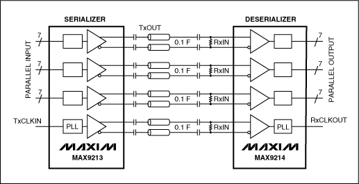
The first generation of LVDS transmission devices (such as MAX9213 / MAX9214) have been installed in the car, which can provide one clock output and three data, using the LVDS transmitter / receiver to connect to the navigation display (Figure 1). Three parallel outputs need to reach the rate required for image transmission, and the clock is used for synchronous transmission.

Figure 1. The first generation LVDS transceiver has 8 outputs.
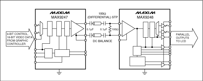
The defect of the first generation LVDS device is that it requires four pairs of twisted pairs (8 outputs) to achieve the required data transmission rate. The 8 data lines make the mechanical structure complicated and difficult to install. Compared with a pair of transmission lines Much higher. The second-generation LVDS devices have improved this, such as the MAX9247 / MAX9248 (Figure 2), which uses a pair of twisted-pair wires to simultaneously transmit data and clock.

Figure 2. The second generation LVDS transceiver has 2 outputs.
An important function of the second generation chipset is the ability to select the capacitive output coupling method, which is usually not available in LVDS devices. Using this coupling method can avoid the problem of ground potential deviation between the transmitter and the receiver. When DC coupling is used, this potential difference may cause data to be unable to be transmitted, or even generate excessive current to damage the device.
When using capacitor decoupling, it is necessary to ensure that the sent data does not charge the capacitor for a long time in one direction. For example, this situation can occur when sending a long series of "1". Second-generation devices such as the MAX9247 or MAX9248 use "DC equalization" technology to solve the above problems. When it is detected that there is a long string of 1s or 0s in the transmitted data, part of the data will be inverted and sent. When the data arrives at the receiver, this part of the data is inverted again to restore the original format. In this way, overcharging of the capacitor can be avoided, and the transmitter will notify the receiver whether each batch of data is sent in the normal format or the inverted format.
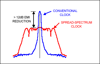
The speed of the second generation device can reach 42MHz, and the data rate is up to 1.15Gb. The increase in clock frequency leads to stronger electromagnetic radiation, and spread spectrum transmission technology can be used to reduce EMI. Spread spectrum technology adds jitter to the clock frequency to spread the original peak EMI energy over a wider frequency band. Since the energy is unchanged, the maximum peak value of EMI is reduced (Figure 3).

Figure 3. Spread spectrum technology reduces EMI.
The second-generation LVDS data transmission device is mainly designed for large-screen applications. The connection of various cameras inside the car does not require a very high transmission speed. For this application, Maxim's third-generation LVDS device uses a low clock rate and reduces the width of the parallel data bus.
The third-generation device is used to control the transmission of data (mainly used for the connection of the camera, but also for the display), used to set the brightness and contrast of the display, or the sensitivity of the camera. Currently, CAN, LIN, or UART transmission buses are used in the system. These solutions require more devices and cables, occupy more space, and cost more. The third-generation devices will use the LVDS interface to transfer control data and avoid using other interfaces.
The fastest change in the format of new automotive electronic signals is video. A few years ago, the video display in in-vehicle equipment was limited to the small-size display screen of the navigation system. To be precise, it was just a navigation electronic device. The monitor plays TV signals. The output of the video signal from the TV receiver to the monitor needs to be transmitted over a long distance. The image format is an analog signal called composite video baseband signal (CVBS).
In recent years, with the development of automotive electronic technology, great progress has been made in the development of video sources, display devices, and video transmission lines. This article discusses related development trends.
Separate the navigation display from the electronic system so that the display can be installed in a position that is easy for the driver to observe. This separation requires the addition of a video transmission line. Now, as more and more display devices are installed on the car, including an electronic dashboard for displaying speed, speed, car status, rear seat multimedia player (passengers can watch TV or DVD, etc.), each display needs Video transmission line.
The new generation of cars may also be equipped with various cameras for driving assistance, such as rearview mirror cameras, night vision goggles, and road sign recognition cameras, and each camera needs to be connected to a display device through a video transmission line.
The rapidly increasing transmission lines inside the car body, especially these transmission lines are getting longer and longer, making the transmission of analog CVBS signals very difficult. These signal formats cannot withstand the electromagnetic interference of the car. At the same time, the large screen display and higher and higher resolutions further aggravate the video interference (such as multipath interference).
One way to reduce video interference is to replace analog signals with digital signals. The video signal line itself cannot generate interference. It has been proved that Low Voltage Differential Signaling (LVDS) can provide the most reasonable connection for digital video transmission. The small signal amplitude (0.35V) and differential structure enable the LVDS transmission line to have minimal electromagnetic radiation.
The first generation of LVDS transmission devices (such as MAX9213 / MAX9214) have been installed in the car, which can provide one clock output and three data, using the LVDS transmitter / receiver to connect to the navigation display (Figure 1). Three parallel outputs need to reach the rate required for image transmission, and the clock is used for synchronous transmission.

Figure 1. The first generation LVDS transceiver has 8 outputs.
The defect of the first generation LVDS device is that it requires four pairs of twisted pairs (8 outputs) to achieve the required data transmission rate. The 8 data lines make the mechanical structure complicated and difficult to install. Compared with a pair of transmission lines Much higher. The second-generation LVDS devices have improved this, such as the MAX9247 / MAX9248 (Figure 2), which uses a pair of twisted-pair wires to simultaneously transmit data and clock.

Figure 2. The second generation LVDS transceiver has 2 outputs.
An important function of the second generation chipset is the ability to select the capacitive output coupling method, which is usually not available in LVDS devices. Using this coupling method can avoid the problem of ground potential deviation between the transmitter and the receiver. When DC coupling is used, this potential difference may cause data to be unable to be transmitted, or even generate excessive current to damage the device.
When using capacitor decoupling, it is necessary to ensure that the sent data does not charge the capacitor for a long time in one direction. For example, this situation can occur when sending a long series of "1". Second-generation devices such as the MAX9247 or MAX9248 use "DC equalization" technology to solve the above problems. When it is detected that there is a long string of 1s or 0s in the transmitted data, part of the data will be inverted and sent. When the data arrives at the receiver, this part of the data is inverted again to restore the original format. In this way, overcharging of the capacitor can be avoided, and the transmitter will notify the receiver whether each batch of data is sent in the normal format or the inverted format.
The speed of the second generation device can reach 42MHz, and the data rate is up to 1.15Gb. The increase in clock frequency leads to stronger electromagnetic radiation, and spread spectrum transmission technology can be used to reduce EMI. Spread spectrum technology adds jitter to the clock frequency to spread the original peak EMI energy over a wider frequency band. Since the energy is unchanged, the maximum peak value of EMI is reduced (Figure 3).

Figure 3. Spread spectrum technology reduces EMI.
The second-generation LVDS data transmission device is mainly designed for large-screen applications. The connection of various cameras inside the car does not require a very high transmission speed. For this application, Maxim's third-generation LVDS device uses a low clock rate and reduces the width of the parallel data bus.
The third-generation device is used to control the transmission of data (mainly used for the connection of the camera, but also for the display), used to set the brightness and contrast of the display, or the sensitivity of the camera. Currently, CAN, LIN, or UART transmission buses are used in the system. These solutions require more devices and cables, occupy more space, and cost more. The third-generation devices will use the LVDS interface to transfer control data and avoid using other interfaces.
The FirstPower High Temperature Battery is desgined for apllcation as extreme temperatures version. This series is specifically for application where robust battery performance is required to withstand harsh temperature environment.
We welcome orders with "FirstPower" brand; We are also flexible to accept orders on OEM basis. Contact us now! Your partnership with FirstPower will prove worthy of it.
High Temperature Battery
High Temperature Battery,High Temperature Solar Battery,High Temperature Gel Battery,High Temperature Long Life Battery
Firstpower Tech. Co., Ltd. , https://www.firstpowersales.com