The design methods and ideas of electronic circuits are constantly being updated, and optocoupler circuits are also facing important changes. Although it seems simple, the design of the LED optocoupler circuit can not be taken lightly. For the aging and energy consumption of the LED optocoupler circuit design, the designer also proposes related improvements, and also does the shortcomings of slow response and instability. Improvements have been made.
The main part of the circuit consists of an amplitude detector D1, a capacitor C1 and a Schmitt trigger Q1/Q2 that controls the LED current flowing through the optocoupler. D2 and D3 stabilize the base voltage of Q2 such that its collector current drives the optocoupler. Capacitor C1 is charged through R1, R2, and D1.
In almost all communication cycles, except for the vicinity of the origin, Q1 is on and Q2 is off. Near the origin, the state of the Schmitt flip-flops Q1 and Q2 changes, and Q2 discharges the capacitor C1 with a constant current because the circuit consisting of Q2, D2, D3, R5, and R6 is I=(2&TImes;VD–VBE2)/ R6 stabilizes the current, where VD is the voltage drop across D2 or D3, and VBE2 is the base emitter voltage of Q2.
This article introduces a circuit that can greatly improve the aging and energy consumption of traditional LED optocoupler circuits. The problems existing in the traditional LED optocoupler circuit are analyzed. Obviously, the optimized method for LED optocoupler circuit design will be the first choice. I hope that after reading this article, you can judge the advantages and disadvantages of an LED optocoupler circuit in terms of energy consumption and aging.
Figure 1 shows two common 0V synchronous AC designs. By reducing the optocoupler load resistance, the switch becomes slower and more uncertain, but reduces the LED current of the optocoupler, trying to reduce the energy consumption in the isolated circuit. In order to achieve faster and faster switching, energy efficiency will have to be sacrificed; however, due to the inverse relationship between energy efficiency and AC voltage magnitude, the benefits of this sacrifice are limited.
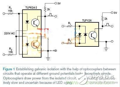
figure 1
The optocoupler LED is in a state of continuous illumination during an approximately full AC cycle, which results in low power consumption efficiency and relatively slow aging of the optocoupler, and means that the over-origin error is too large and almost uncontrollable. The sensitivity range of the circuit is determined by the parameters of the optocoupler. The design of Figure 1 is not an ideal solution. In terms of efficiency, depending on the current conversion rate and AC amplitude of the optocoupler, the output should be able to reach 5 to 100 mA.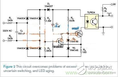
figure 2
The design of Figure 2 overcomes the problem of excessive energy consumption, uncertain switching and LED aging. It is ideal for applications with a wide range of communication. Compared to the circuit of Figure 1, the LED of Figure 2 only illuminates near the origin and receives energy from the pre-charging capacitor, so the average current consumption is reduced by a factor of 10 to 100. The design also provides faster, more deterministic and sharper switches. Even worse, by delaying LED aging. The resistors R1 and R2 in Figure 1 consume no less than 1.5W of thermal power, so external devices can be replaced with 0.1W devices in the same board area (Figure 2).The main part of the circuit consists of an amplitude detector D1, a capacitor C1 and a Schmitt trigger Q1/Q2 that controls the LED current flowing through the optocoupler. D2 and D3 stabilize the base voltage of Q2 such that its collector current drives the optocoupler. Capacitor C1 is charged through R1, R2, and D1.
In almost all communication cycles, except for the vicinity of the origin, Q1 is on and Q2 is off. Near the origin, the state of the Schmitt flip-flops Q1 and Q2 changes, and Q2 discharges the capacitor C1 with a constant current because the circuit consisting of Q2, D2, D3, R5, and R6 is I=(2&TImes;VD–VBE2)/ R6 stabilizes the current, where VD is the voltage drop across D2 or D3, and VBE2 is the base emitter voltage of Q2.
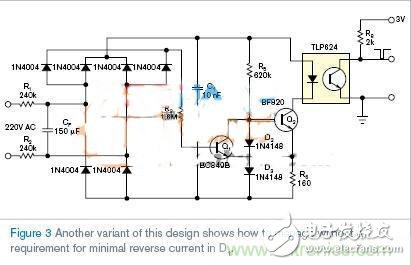
image 3
Some applications do not require the inherent hysteresis of Schmitt triggers; Figure 3 shows such a design. It also shows how to handle the unwanted D1 minimum inversion current. However, the circuit is more suitable for purely synchronous and amorphous thyristor control. Due to the stability of the LED current, these designs extend the range of the input AC voltage, which is beneficial for multi-standard AC power supply designs; another advantage of this design is the ability to have safer features. In the case of a short circuit at its termination, the optocoupler transfers 10 to 100 times less current between the isolated and non-isolated sides than in the Figure 1 circuit. Optocouplers also have advantages. Due to the low duty cycle, the value of the optocoupler load resistor R8 can be arbitrarily reduced without loss of power. This reduction will reduce the origin error.This article introduces a circuit that can greatly improve the aging and energy consumption of traditional LED optocoupler circuits. The problems existing in the traditional LED optocoupler circuit are analyzed. Obviously, the optimized method for LED optocoupler circuit design will be the first choice. I hope that after reading this article, you can judge the advantages and disadvantages of an LED optocoupler circuit in terms of energy consumption and aging.
Xlpe Control Cable,Termite Resistant Control Cable,Termite Proof Control Cable,Termite Proof Xlpe Control Cable
Baosheng Science&Technology Innovation Co.,Ltd , https://www.bscables.com