Received a 29-inch TCL color TV, model AT2990I! Say this machine is different from the AT2990U, only find the U drawing, I did not find, 2 machine CPU is different? The CPU of AT2990U is M37221M6 (see on the drawing), and the CPU of this AT2990I in my hand is M18V3PNICAM. After reading the drawings, the function pins of the two are all the same!
This is a mobile phone, the power supply, standby circuit part of the machine have all been welded! The power supply is STR6708. I have a 10K resistor on the optocoupler. The output line voltage is about 120V. The primary part of the power supply should be normal! Now the fault is powered red light, 5V power supply is normal, the line voltage is about 23V, it looks like standby! There is no original remote control, use the universal remote control to input all the code, press the power button does not respond, including pressing all the buttons on the TV, the red light is still on, the green light does not flash or shine, the CPU's 37 feet to ground voltage is 0. V. There is no change, it looks like the CPU is not working! I removed the TC144 that controls standby, and the voltage of the power-on line is still 23V. Later, the grounding condition of the B pin of the TC144 is also the same! M18V3PNICAM power supply is normal, the remote control receiving part is no problem, the crystal oscillator is 8M, and the fault is still changed. The power supply crystal oscillator 2 foot to ground voltage only has one foot 2V, the other foot only has 0. V voltage, forget it is Input or output! At present, I know only so much data, how can this machine be repaired! How to determine whether the power feedback regulator, standby circuit or CPU does not work? Which components do you want to check in these parts? I hope that experienced masters can guide the younger brother after analyzing the fault, thank you!
Taking advantage of the dry weather today, there are not so many things to do. In the evening, I will not bear to watch the CBA Finals... I saw that the shop is full of people watching the game, the heart is so delicious... Oh... no way! Carefully read the reply of the masters, measured the voltage of each part, basically normal, but it is impossible to boot! It seems that 10 and 9 are CPU problems. Inadvertently found a board with the same machine in a pile of scrap boards, but most of the components were removed. Fortunately, the CPU is still there. ! After disassembling the installed power, the crystal oscillator is on the ground voltage... I am very disappointed... The input is still 2.0V, and the output is only 0. V! But the slight change of the 2 red and green lights at the moment of power-on reminded me! Before the CPU is changed, the green light is not lit, and the red light is on directly! After changing the CPU, the green light flashed for a moment, then the red light then turned on! Is the CPU crystal voltage like this? ? Hurry up and pick up the universal remote control, enter the code 068 (the master said the machine code is 068), then press the switch button... The light bulb is on, the measurement line power supply 135V is normal! Engaged for so long, it turned out that the CPU is hanging! In addition, the crystal 2 foot to ground voltage is like this, input 2.0V, output about 0.7V, almost give these two voltages to the blind ... Disassemble the bulb, connect the upstream fuse, power on, did not hear high voltage Sound, measurement line excitation output, only about 0.3V, it seems that there are other problems... It’s time to get off work, get it tomorrow, and then get it... Hehe
I have time to continue to get in the morning... Ha ha... After changing the CPU last night, I can boot normally, but the line is not motivated, the line is not working, the line is pushed to drive the power supply, there are more than 20 V in standby, but only 4V is left when the line starts. And, the buck resistor is terrible (two 3W4.7K resistors are together, these two resistors are normal, and then connected to B+ on the buck to drive the power supply, this is more common in some high-definition machines in Skyworth)! The heat is big, it means that the current is definitely not small. First check the excitation tube, use the F422, and see it on some old assembly machines. This thing is not too hot, the circuit board is burning a little black, there is no problem with the amount of welding, but with a mouth blowing, the penetration current is not small, this tube performance is not good, first try another, one Time can not find the same, just use 2482 instead of trying it, this is good... Directly without starting, it seems that these 2 tubes can not be replaced! No way, can only find, and finally found a good performance on the block scrap board! But after the installation, the fault remains! Checked the surrounding related components, did not find any problems, and then only 8838 or peripheral problems! Check the 37-pin 8V power supply is normal, just have such a large block in your hand, try changing the block first! In other words, the disassembly is replaced, the power is turned on, and the high-voltage sound that has been long gone is finally coming. The two resistors of the hand model are only slightly warm, and the closed-circuit image is connected. The picture tube looks good! At the end of the repair, although it took a lot of time, but the value, the experience is such a little accumulation
The following is the drawing of AT2990U, I can't find TCL AT2990U drawings.pdf
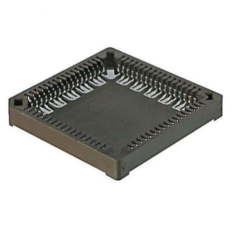
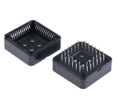
Antenk PLCC connectors Series Sockets are low profile, thin wall sockets designed to convert plastic leaded chips to a thru-hole PCB format on a .100" centerline grid.Antenk's superior precision stamped contact design provides consistent, high retention contacts for all size chips.

PLCC Connectors -PLCCSockets
A PLCC socket is a component that connects a chip carrier to an electronic circuit via surface-mounting or through-hole technology.
Plastic leaded chip carriers (PLCCs) are used in surface-mount technology where electronic circuits are produced, and components need to be mounted or placed directly onto a printed circuit board (PCB). The chip carrier is placed in a PLCC socket, which is either surface-mounted or features through-hole technology. A specialised tool called a PLCC extractor is needed to remove the chip carrier from the PLCC socket.
What are PLCC sockets used for?
PLCC sockets are used in surface-mount device (SMD) and surface-mount technology (SMT) applications. PLCC sockets made of heavy gauge copper alloy are compatible in high shock / high vibration applications. PLCC sockets made of rolled-leaf copper are useful in low-cost computer applications.
Types of PLCC sockets
The two primary categories of PLCC sockets are:
Surface-mount PLCC sockets, which are used in devices sensitive to heat from the reflow process. These allow for component replacement without redesigning or reworking the entire PCB.

Through-hole technology PLCC sockets are necessary when a device requires stand-alone programming with flash drives or memory devices. These are also beneficial for prototyping activities where wire wrapping is required.

Plcc Socket,Plcc Connector,Plcc Socket Connector,Smd Plcc Connector,PLCC Connector DIP,PLCC Connector SMT
ShenZhen Antenk Electronics Co,Ltd , https://www.antenksocket.com