Introduction
What is used in this project? Superfluid RGBLED common anode and PIC18F25K20 to produce a combination of colors. It has two functional modes, the automatically generated color sequence is stored in μC memory, and the manual mode can be selected in one of the seven possible colors.
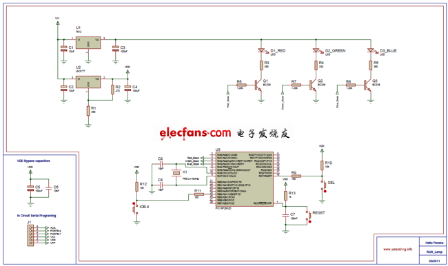
Schematic
firmware
PWM (Pulse Modulation) controls the RGB LED. Since the PIC18F25K20 has only 2 PWM outputs (hardware), I also have 3 PWM output software. I use TIMER0, I use the manual mode PWM flat change interrupt.
Debounce
In this project, I use buttons to change between the two modes and change the color. However, if we use the buttons in the circuit (1) we have a problem. This configuration problem is due to the mechanical nature of any switch that may contain returning some action. To solve this problem, it can be done by hardware or software. We can do this with an RC delay circuit or with a Schmitt trigger, but both ways will increase the price. So, I am doing a software bounce.
Code example for doing a bounce:
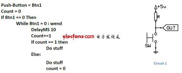
It can be at different distances, but this way works for me.
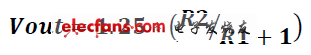
Power Supplier
I used a 7812 regulator, the voltage is stable and kept in the RGB LED μC I used the LM317 voltage regulator. To calculate the output of the LM317, I use this formula:
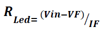
LED RGB
I use a different resistance value for the RGB LED because its color has a different VF (forward voltage). I use these equations to calculate the resistance:
Submersible Motor Winding Wire
D TYPE
HENAN HUAYANG ELECTRICAL TECHNOLOGY GROUP CO.,LTD , https://www.huaonwire.com