I. INTRODUCTION <br> With the rapid development of communication systems, all countries are accelerating the pace of 4G network development. The advantages of higher speed, better quality and more flexibility make the 4G network unparalleled. The high data transmission rate and multi-mode transmission have a great impact on the communication system. The complex modulation method undoubtedly puts higher linearity requirements on the core module power amplifier in the base station, and also requires higher channel bandwidth, PA. Research has also become a hot research area today. DXY Dingxin has also invested heavily in microwave radio frequency research, covering wireless communication (relay, base station, RRU, WLAN), WIFI, CMMB, ISM (industrial, scientific, medical), etc. The laboratory has become the application engineering laboratory of NXP and Tsinghua University Microelectronics Research Institute. The reverse Doherty power amplifier designed in this paper is one of the products.
As a core component of the transceiver, the PA accounts for about one-third of the system's energy consumption. The traditional base station power amplifier improves the linearity by simply reducing the efficiency of the power amplifier by power back. In order to reduce the operating costs of communication operators, it is urgent to follow the development trend of green communication and improve the efficiency of PA. The traditional DPA can provide sufficient efficiency in a certain range of power backoff, which is especially important for DPA research. Compared with the traditional DPA, the 1/4 wavelength transmission line after the IDPA structure peak amplifier can compensate the phase and reduce the power leakage, further improving the power amplifier efficiency.
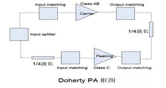
Second, the working principle of IDPA <br> The traditional DPA includes carrier power amplifier and peak power amplifier, the carrier power amplifier works in class B or class AB, and the peak power amplifier works in class C. The carrier amplifier is always working, and the peak power is turned on when it is turned on. When the carrier power amplifier reaches saturation and the peak power amplifier is about to start working, the efficiency reaches 78.5% of the theoretical maximum value of the class B power amplifier. As the input signal is gradually increased, the peak power amplifier is turned on, thereby reducing the apparent impedance of the carrier power amplifier, which is equivalent to a negative impedance connected in series to the carrier power amplifier. At this time, the carrier power amplifier is always in a saturated state, and its output voltage is constant. As the output impedance is continuously reduced, the output current of the carrier power amplifier is also continuously increased. When the peak power amplifier reaches saturation, its efficiency also reaches its maximum. A Class B power amplifier can reach the maximum efficiency when it is peaked, and this Doherty power amplifier can achieve the maximum efficiency only at half the peak value.
The 1/4 wavelength transmission line behind the carrier power amplifier acts as an impedance converter, and also causes the two power amplifiers to have a 90° phase difference. In order to make the two power amplifier outputs in phase, it is necessary to supplement the 90° phase shift before the peak power amplifier. The block diagram of the DPA is as follows:
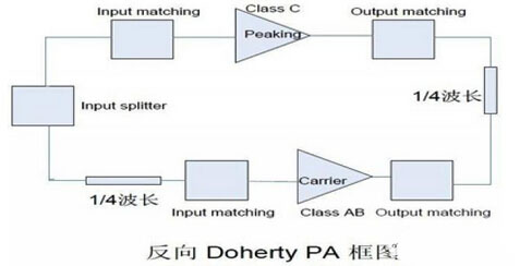
Compared with the traditional DPA structure, the IDPA structure's 1/4 wavelength transmission line is added behind the peak power amplifier, which can reduce the power leakage while improving the power amplifier efficiency. The IDPA structure is shown below.
For DPA technology, the peak amplifier is turned on when the carrier amplifier is saturated, so that the efficiency of the power is always maintained at a high level within a certain range of back-off, and does not fall sharply.
During the small signal phase of operation, the carrier amplifier is operating normally and the peak amplifier is off.

Assuming that the carrier power amplifier and the peak power amplifier are equal power inputs, the output impedance Z1 of the carrier power amplifier is gradually reduced by 2R, so that more power can be output, so that the efficiency of the IDPA is always maintained at a high level, and the power is not retracted. Within a certain range, efficiency has dropped dramatically. Since the circuit networks of the two power amplifiers are the same, there will be the same output power and the same amount of current output. At this time, Z1=Z2=Z3=Z0=R=50 ohms.
III. Design of IDPA <br> The power amplifier tube used in this design is NXP's BLF8G27LS-100P. The carrier amplifier works in class AB, the gate voltage is 1.99V, the peak amplifier is in class C, and the gate voltage is 0.67V.
Design input and output matching circuits for different saturation powers and efficiencies. The drain adopts a bilateral balanced feed structure, and the circuit is composed of an RF filter capacitor, an envelope frequency decoupling capacitor and a 1/4 wavelength microstrip line. The length of the microstrip line can be adjusted according to the performance of the power amplifier, and the envelope frequency is short-circuited as much as possible. Voltage. By optimizing the bias circuit network, the effect of the memory effect is further reduced, and the video bandwidth VBW is increased to improve the broadband characteristics of the power amplifier.
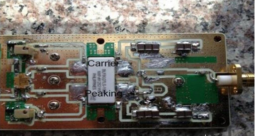
The optimal load impedance of the power amplifier tube will change with the input power. Under the specific power and efficiency requirements, the input and output matching network and the bias circuit network can be adjusted to achieve a good compromise between power and efficiency. . The physical circuit of this design is optimized as shown below
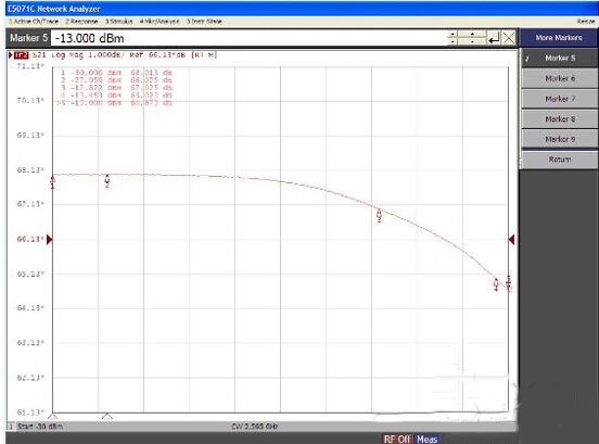
Fourth, test results analysis <br> Test 2500MHz, 2595MHz, 2690MHz AM-AM curve in the 2500MHz-2690MHz frequency range,
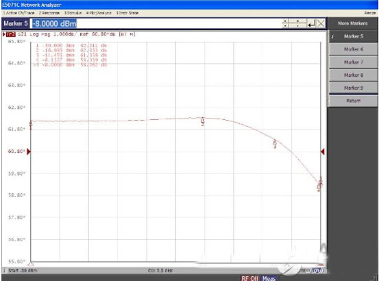
2500MHz AM-AM
2595MHz AM-AM
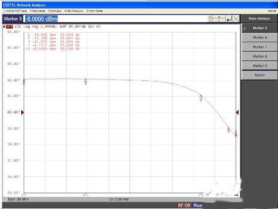
2690MHz AM-AM can be seen from the above AM-AM curve, the gain fluctuation is about 0.1dB in the range of input power -30dBm -16dBm, and the power amplifier gain linearity is better.
Test with WCDMA single carrier signal with a peak-to-average ratio of 10.3dB
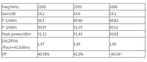
The above table shows the gain, power and efficiency, gain fluctuation of 0.5dB in the range of 2500MHz-2690MHz, and the consistency of power and efficiency in the whole frequency range is good, which shows that the PA can meet the wide bandwidth requirement.
Test ACP with WCDMA four-carrier signal with 19.84MHz bandwidth

V. Conclusions <br> For the 4G-LTE broadband signal with peak-to-average ratio, this paper designs a reverse Doherty power amplifier using NXP (NXP) BLF8G27LS-100P power amplifier tube to ensure that the power amplifier efficiency is maintained at a higher value. At the same time, it also got a better linearity, which indicates that the power amplifier can be well applied to various communication systems such as 4G-LTE.
UK Surface Tabletop Socket be with American type plug,could be selected to be with USB ports,Internet ports,Phone ports,overload protection and with or without switch.
US Surface Tabletop Socket can be set into furniture and office furniture like table,cabinet and so on.It will be easily to use the charging for Phone and home appliance.
Specifically, We have our own design and production team for USB Circuit Board design and produce.
US Surface Tabletop Socket
Power Outlet Strip,USSurface Tabletop Socket,USA Surface Mounted Power Strip,USSurface Mounted Power Strip
Dongguan baiyou electronic co.,ltd , https://www.dgbaiyou.com