Since the advent of digital image processing, it has been a cutting-edge research discipline, and it has been enduring for a long time. At the same time, with the advent of the digital age, the market is increasingly demanding digital image processing. Therefore, this project ------ FPGA-based multi-function digital image acquisition and processing platform is designed for a variety of equipment and applications that require digital image processing, for example, medical CT, X-ray, etc. Image enhancement and processing; various digital devices that need to support image optimization. At the same time, this platform can also be used for design reference and teaching demonstration of digital image processing related courses.
1.2 Project AdvantagesThe FPGA-based multi-function digital image acquisition and processing platform is a versatile, versatile digital processing platform that offers the following advantages over other similar designs:
1 Designed with a programmable FPGA to facilitate design updates and reduce the cost of upgrades;
2 The platform is implemented in hardware, which is faster than the software implementation method using DSP;
3 Each module is independent of each other, which is convenient for reuse of design and can be used for other projects after simple processing;
two. Demand Analysis 2.1 Functional AnalysisAccording to the design goals of this project, the functions that this design needs to accomplish are:
(1) Basic image enhancement, image smoothing, image sharpening, histogram equalization, histogram normalization, etc. can be performed on the input digital image, and frequency domain related Butterworth filtering, Gaussian filtering, etc. can also be performed.
(2) Advanced processing such as image edge detection can be accomplished by combining various basic image processing procedures.
(3) YCrCb format image data converted by CMOS sensor can be input and converted to RGB format.
(4) The image data of the digital image processor can be processed through the USB interface.
(5) The processed image can be saved in Flash, and the image generated during the processing can be displayed through VGA.
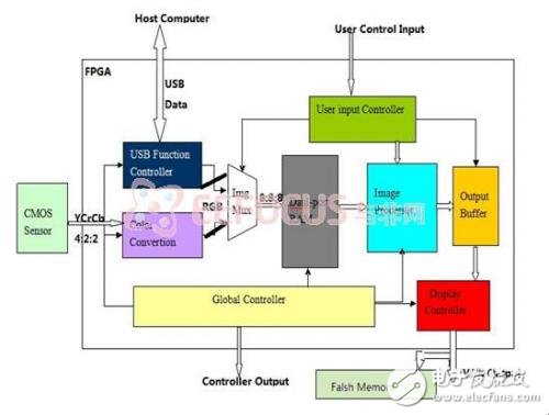
three. Solution design 3.1 System function realization principleThis design uses Xilinx's Nexys 3 Spartan-6 FPGA Board development board, which uses the large-capacity logic resources of the Xilinx Spartan®-6 FPGA (XC6LX16-CS324) to complete each module. The overall hardware block diagram of this design is shown in Figure 1. It can be clearly seen from Fig. 1 that the system is mainly composed of a USB device control unit, a color space conversion unit, a user control input unit, an overall control unit, a dual port RAM control unit, a flash control unit, a display control unit and an image processing unit.
The working principle of the system is as follows: the overall control unit selects the data source of the dual port RAM input terminal according to the user control input unit, and then the image processing unit reads out the data according to the output signal of the user control input unit to perform related processing on the image and output to the display RAM. Medium, displayed by the display control unit to the VGA, and saved to Flash according to user input. Please refer to the specific description of each unit module.
3.2 Hardware platform and resource configuration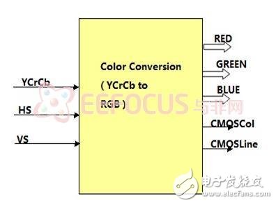
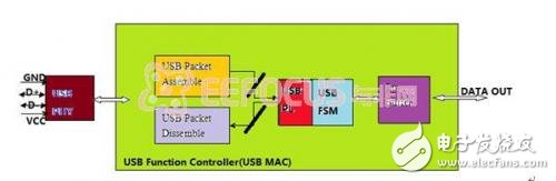
The USB control unit is one of the sources of data for the entire system and occupies an important position in the system. Let us first look at the block diagram of its composition, as shown in Figure 2.

As can be seen from the above figure, the USB control unit is mainly composed of USB Packet Assemble/Dissemble, USB PL, USB FSM, and EP Buffer. USB FSM mainly implements USB function devices and communicates with Host Computer; USB Packet Assemble/Dissemble mainly completes unpacking and packaging of USB data packets, USB PL (USB Protocol Layer) implements USB protocol; and the module communicating with USB PHY is not drawn. Out.
3.2.2 Color Space Conversion UnitThe color space conversion unit performs an operation of converting CMOS input YCrCb format data into RGB data, and its composition block diagram is shown in FIG.
The format converted from YCrCb to RGB is as follows:
R = Y + 1.371 * (Cr - 128);
G = Y - 0.698 * (Cr - 128) - 0.336 * (Cb - 128);
B = Y + 1.732 * (Cb - 128);
Due to the special nature of the hardware implementation, the above formula is changed to:
R = Y + 1403 * ( Cr - 128 ) /1024;
G = Y - 714* ( Cr - 128 ) /1024 - 344 * ( Cb - 128 ) /1024 ;
B = Y + 1773 * ( Cb - 128 ) /1024;
3.2.3 Image Processing UnitThe image processing unit is the most important unit in the system, mainly for digital image processing related tasks such as histogram equalization, image sharpening, and frequency filtering. Its block diagram is shown in Figure 4:
The image processing unit has basic digital image processing modules such as histogram equalization, image sharpening, and frequency filtering, which can be combined according to the user's choice to accomplish a specific task or purpose (such as image edge detection, etc.). .
3.2.4 Other control unitsOther control units such as the overall control unit, the user input control unit, the dual-port RAM control unit, and the Flash control unit mainly perform operations such as control and flow control during system operation.
3.3 System FlowchartFrom the analysis of each module of the above system, the function of each module and the overall architecture of the system have been fully understood. Now let us introduce the overall operation process of the system.
The overall system flow chart is shown in Figure 5:
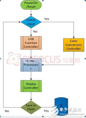
The above figure is a simplified system flow chart showing the main path through which data flows through the system. After the power-on initialization, the data source of the dual-port RAM input terminal is selected according to the user control input unit, and then the image processing unit reads the data according to the output signal of the user control input unit to perform related processing on the image and output to the display RAM, and the display control unit Displayed to VGA and saved to Flash based on user input.
2.3 After fermentation Orange (Orange made enzyme solution navel orange), seized after the hand, breaking and other processes made of navel orange sauce.
Effects: lung, spleen shun gas, without any food additives, preservatives, is the first choice of children and senior citizens.
Companies registered capital of 35 million yuan, the end of 2014 the total assets of 48.69 million yuan, including fixed assets of 37.52 million yuan. The company's existing cooperation Orange cultivation base 7043.5 acres, the company production base is located in Jiangxi County Tech Industrial Park Chu Tan industrial area, covers an area of 120 acres, it has built a standard plant 9,000 square meters, Nissan 6000 kg Orange enzymes and other liquid enzyme products. Enzyme, known as enzyme, refers to a polymer substance having biocatalytic functionality. In the catalytic reaction system an enzyme, the reactant molecules are known as substrates, enzyme substrates by catalytic conversion to another molecule. Almost all cellular activity of enzymes involved in the process are required to improve efficiency. Similar to other non-biological catalysts, enzymes chemical reactions by lowering the activation energy to accelerate the rate of the reaction, most of the enzyme catalyzed reaction rate can be increased a million times; in fact, the enzyme is to provide an activation energy needs than another low way, so that more particles to have less than the activation energy of the reaction kinetic energy, thus speeding up the reaction rate. Enzyme as a catalyst, in itself is not consumed during the reaction, it does not affect the chemical equilibrium reactions. Positive enzyme catalysis, but also a negative catalytic effect, not only to accelerate the reaction rate, but also to reduce the reaction rate. And other non-living catalysts is different, having a high degree of specificity of enzyme, only a catalytic reaction or produce a particular specific configuration.
Enzyme Cream,Whitening Slimming Enzyme Cream ,Meal Replacement Diet Enzyme Cream ,Conditioning After Surgery Enzyme Cream
Guangdong ganzhou , https://www.tlqcjs.com